...Then again - I cannot afford those Utopias anyway...
Into same wagon here : ) but another fine one think should be within reach saving up over some time, and for my eye in links below it looks nearly the same for all curves except the cheaper one is actually smoothest in response and impedance curves and maybey a bit closer to researched Harman curve.
https://www.innerfidelity.com/images/FocalUtopia.pdf
https://www.innerfidelity.com/images/SennheiserHD650.pdf
I have never heard tube headphone amps before - but have to say, headphones is a perfect fit because you only need 1w of Class A sound. They actually sound very similar to Silicon Harmony.
Do I sense an XRK tube design coming down the pike?
That event looks like it was fun. Glad your amps were well-received.
I actually have a hybrid tube amp design by Sodacose in the works. It's very similar to the PCA, but uses a tube instead of a JFET. I also have to build, one of these days, the inspiration for the Silicon Harmony: the Glass Harmony by Hugh Dean, a 28w into 8ohms SE Class A tube/mosfet hybrid amp. I think Hugh says that it is still the best amp he has heard ever.
Here is the design by Sodacose:
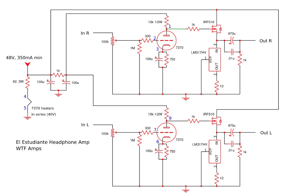
Here is the design by Sodacose:
Attachments
Last edited:
...the cheaper one is actually smoothest in response and impedance curves and maybey a bit closer to researched Harman curve.
https://www.innerfidelity.com/images/SennheiserHD650.pdf
Hey BYRTT - so you recon if we EQ the HD650 to the Harman curve we are in audiophile Utopia anyway - for cheaper?
Last edited:
...the Glass Harmony by Hugh Dean, a 28w into 8ohms SE Class A tube/mosfet hybrid amp. I think Hugh says that it is still the best amp he has heard ever.
Wow, this must be something special. I see it is an old design. Any schematics?
Hey BYRTT - so you recon if we EQ the HD650 to the Harman curve we are in audiophile Utopia anyway - for cheaper?
Yes but also if we don't EQ anything because if you look closer on those curves between 3-10kHz Focal Utopia have much more resonance and above 10kHz it has much more comb filtering or resonances going on plus its impedance curve is bit less smooth than HD650, of course both can be EQ'ed to Harman curve but HD650 would need less and broader correction. I haven't either of them or ever held them in my hand so cannot comment on the Ferrari note other than Ferrari's is expensive but on paper for me HD650 looks better, and then comes the amp : ) Personal is interested in HD650 because of measured data and the high impedance plus its possible to save up for it and get a pair sometime next year.
I think Byrtt is on-point. Mere mortals like us, can save all we want but won't ever have enough for a LaFerrari 
One other more reasonably priced headphone that sounded really nice when driven by my Silicon Harmony was the HiFiman HE-400. It's a planar drive so had nice attack. Bass is very full - perhaps more so that Byrtt may like. The Audeze LCD-X was also excellent sounding but very large and heavy.
One other more reasonably priced headphone that sounded really nice when driven by my Silicon Harmony was the HiFiman HE-400. It's a planar drive so had nice attack. Bass is very full - perhaps more so that Byrtt may like. The Audeze LCD-X was also excellent sounding but very large and heavy.
Wow, this must be something special. I see it is an old design. Any schematics?
Sorry, no public schematics for what remains to be the epitome of great musical sound from the Master of Musicality, Hugh Dean.
StellarE:
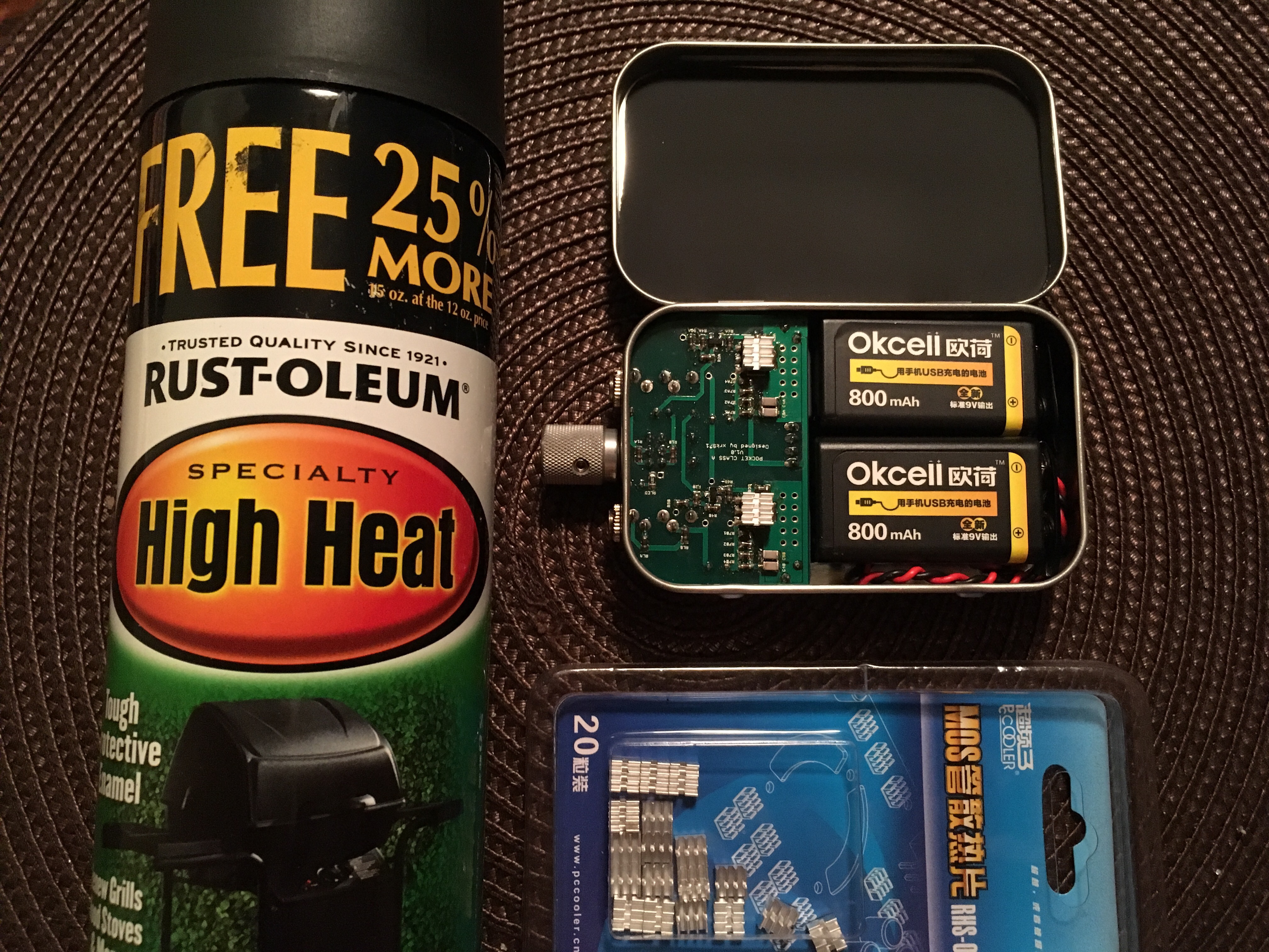
Wow, that's a nice looking unit - very clean. Black paint is usually very good - but harder to apply than Kapton tape. You should get a roll of that stuff. Will last for years. Just noticed you probably live in the zone of totality for the Eclipse on Aug 21! That's the event of a lifetime to see a total solar eclipse in the zone of totality. I'm jealous. Have fun - last time one this good was in USA was 1917.
Wow, that's a nice looking unit - very clean. Black paint is usually very good - but harder to apply than Kapton tape. You should get a roll of that stuff. Will last for years. Just noticed you probably live in the zone of totality for the Eclipse on Aug 21! That's the event of a lifetime to see a total solar eclipse in the zone of totality. I'm jealous. Have fun - last time one this good was in USA was 1917.
Hi folks,
I discovered that thread some days ago during my vacation. I spent one full night reading the 110+pages
To introduce myself, I'm a physicist and part of my work is to design very low noise amps, mostly integrators with or without analog shaping. I'm more in the 100kHz to 50 MHz range than audio though.
I've been using the BF862 for 10+ years as a front end jfet for my low frequency amps. For the 10+ MHz devices, I often use GAAS FET.
For those reasons, I'm not used to the 1000+ uF caps. BTW, I never put any electrolytic cap in my amps. clearly a different world.
If you agree, I'll design my own PCB without the battery operation. I'll use the extremely low noise LDO I'm used to and a wall plug 18V regulated power supply. I plan to actually use 2 LDOs to avoid cross talk.
Now my question about that nice audio preamp. I do think that I follow the amp topology but I'm slightly concerned about the MOSFET choice. xrk971, what drove you toward that big MOSFET usually exploited in real power systems (I mean amps) ?
Hi folks,
I discovered that thread some days ago during my vacation. I spent one full night reading the 110+pages
To introduce myself, I'm a physicist and part of my work is to design very low noise amps, mostly integrators with or without analog shaping. I'm more in the 100kHz to 50 MHz range than audio though.
I've been using the BF862 for 10+ years as a front end jfet for my low frequency amps. For the 10+ MHz devices, I often use GAAS FET.
For those reasons, I'm not used to the 1000+ uF caps. BTW, I never put any electrolytic cap in my amps. clearly a different world.
If you agree, I'll design my own PCB without the battery operation. I'll use the extremely low noise LDO I'm used to and a wall plug 18V regulated power supply. I plan to actually use 2 LDOs to avoid cross talk.
Now my question about that nice audio preamp. I do think that I follow the amp topology but I'm slightly concerned about the MOSFET choice. xrk971, what drove you toward that big MOSFET usually exploited in real power systems (I mean amps) ?
Sdouble, welcome on board!
Interesting but do you plan to use for music or are you making another scientific amp for instrumentation? I have had one user so far use this as a low noise preamp in his engine research lab at university. He said there is not a quieter preamp.
LDO regulators work well / I have tried a few. Currently using one from TI that has programmable jumpers that set voltage and noise is less tha 4uV according to specs. It's PSRR when fed by linear trafo is still not as good as what I can achieve with a SMPS step up and cap multiplier followed by CRCRC (-120dB ripple of 60Hz mains).
Why ZVN4306 for output mosfet? It is small SMT and has good current carrying capability. Others can work there - it's not critical. I have used IRF610 and even large BJT like 2SA1837. I have also used 4 BF862's in parallel with 4 BF862's as CCS, and two BF862's on the input stage. That was an earlier amp.
Matching 8 x BF862's per channel is a pain though.
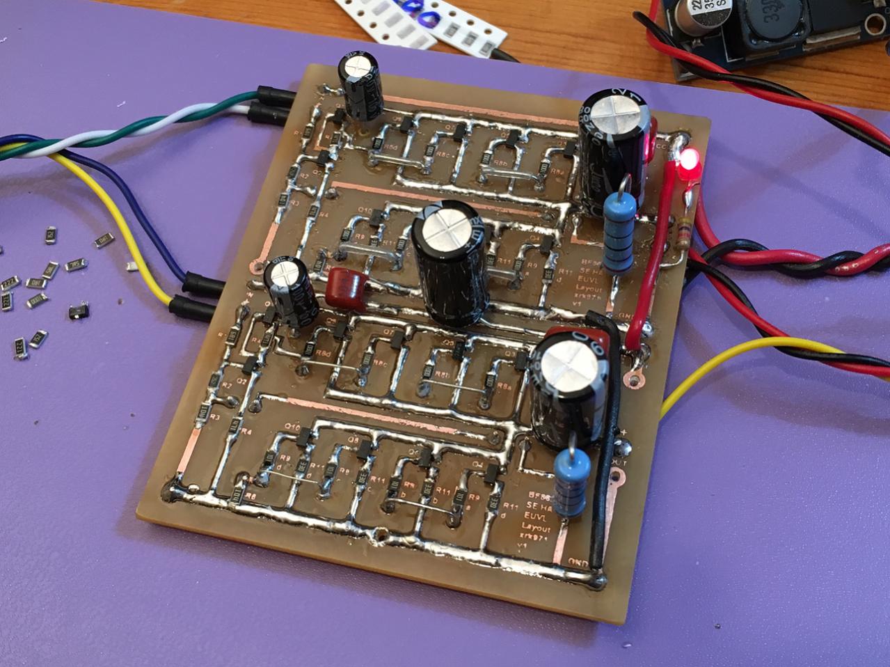
BF862 based SE Class A Headamp without the HEAT
XRK, sorry if I was not clear. What I do at work is something different. Here I intend to use the preamp as a audio preamp . to listen for music .. at work.
I'll order a Beyerdynamic DT 770 PRO, 250 ohms to couple to your preamp. I'll see what that gives with my desktop oudio output.
I'll order a Beyerdynamic DT 770 PRO, 250 ohms to couple to your preamp. I'll see what that gives with my desktop oudio output.
Sdouble, welcome on board!
LDO regulators work well / I have tried a few. Currently using one from TI that has programmable jumpers that set voltage and noise is less tha 4uV according to specs. It's PSRR when fed by linear trafo is still not as good as what I can achieve with a SMPS step up and cap multiplier followed by CRCRC (-120dB ripple of 60Hz mains).
XRK, may i suggest you to have a look at the LT3042 PSRR curve ?
LT3042 is my working horse
XRK, may i suggest you to have a look at the LT3042 PSRR curve ?
LT3042 is my working horse
Thanks, I will give the LT3042 a try. 200mA is good for such a low 0.8uV noise level and 79dB PSRR not bad either. So if I give it something with already having ripple at -40dB then should give -120dB overall. A linear trafo with larger 22mF/3.3R/22mF CRC should get me to about 1mV ripple under a 100mA load. Then feed the LT3042 with it.
Did you need any PCB's for your desktop amp? I got a new batch of 50 that came in a few weeks ago. You are certainly welcome to design your own PCB, but why when you can get a proven one that works for $15? Also, if you do make your own, please share in another thread in the headphone amps forum or SS forum, whatever you feel appropriate, but this thread is for the xrk GB version.
Last edited:
Actually, properly configured, LT3042 provides you with almost 120 dB PSRR at 60 Hz. Do you need more than that starting from a reasonnable regulated SMPS ?Thanks, I will give the LT3042 a try. 200mA is good for such a low 0.8uV noise level and 79dB PSRR not bad either.
I don't know yet. My idea was to design my own PCB. I have my habits (getting old obviously). Moreover, I'd like to design a unique PCB with all fonctionnalities embedded.Did you need any PCB's for your desktop amp? I got a new batch of 50 that came in a few weeks ago.
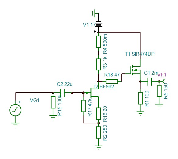
simulation with another MOSFET
everything is in the title
DC values are very similar.
BF862 runs a 8mA roughly
here are some simulation results:
first : scheme
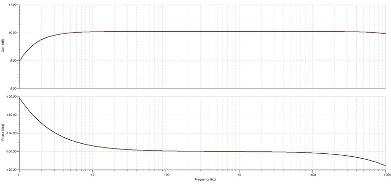
then, ac transfer function
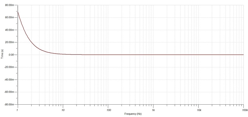
group delay
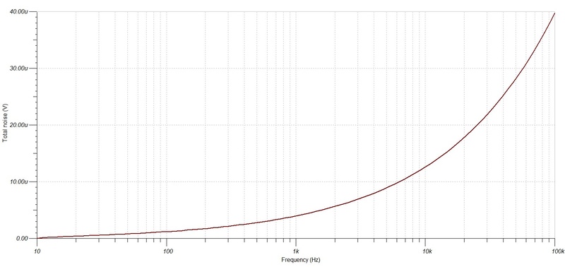
cumulated noise
that MOSFET exhibit a much stronger transconductance leading to a lower output impedance.
everything is in the title
DC values are very similar.
BF862 runs a 8mA roughly
here are some simulation results:
first : scheme
then, ac transfer function
group delay
cumulated noise
that MOSFET exhibit a much stronger transconductance leading to a lower output impedance.
Last edited:
That looks familiar - the 8mA bias on the BF862 may be a tad high but probably fine. It will depend on large part, the actual BF862 variations. I have tested hundreds of them with an in situ bias current test rig and then try to match left and right channels for bias current at the same exact conditions. Interesting mosfet - never heard of it but if you say transconductance is low, should be good.
- Home
- Group Buys
- xrk971 Pocket Class A Headamp GB