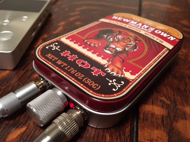
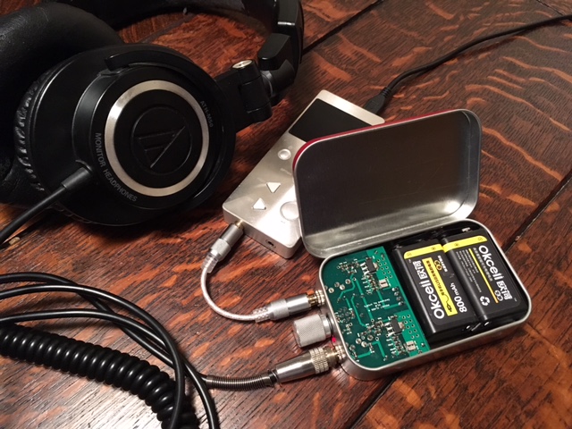
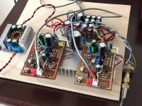
Been big is better naughty today : )
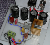
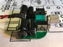
Input=220uF and output=2200uF Panasonic FC (no bypass caps at all):
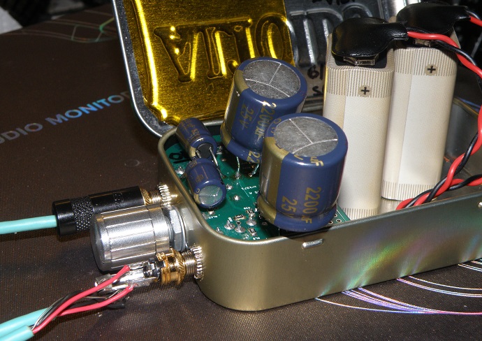
Before using that FC 2200uF at output had a FR 2200uF in there, but it was not good sound probably because its form was so thin in diameter but very long.
After looking at impedance curve for that FC 2200uF thinking was that a few ohms difference will make PCA loading distort group delay as curve looks, maybe not in mS but at least in uS or nS, so based on that curve made a FIR convolution filter that is very mild reverse in timing changing phase only up to about 5,2º without touching amplitude domain at all.
With this capacitor specific filter loaded sound was improved to more natural sound and rhythm, so tomorrow task will be try same light phase change receipt for OB-1 driver units impedance curve : )
Should down the road anybody want to try this filter all it needs is we use same capacitor value and/or brand at output, then i can share convolution file.
Input=220uF and output=2200uF Panasonic FC (no bypass caps at all):
Before using that FC 2200uF at output had a FR 2200uF in there, but it was not good sound probably because its form was so thin in diameter but very long.
After looking at impedance curve for that FC 2200uF thinking was that a few ohms difference will make PCA loading distort group delay as curve looks, maybe not in mS but at least in uS or nS, so based on that curve made a FIR convolution filter that is very mild reverse in timing changing phase only up to about 5,2º without touching amplitude domain at all.
With this capacitor specific filter loaded sound was improved to more natural sound and rhythm, so tomorrow task will be try same light phase change receipt for OB-1 driver units impedance curve : )
Should down the road anybody want to try this filter all it needs is we use same capacitor value and/or brand at output, then i can share convolution file.
Attachments
Last edited:
...Just made a simple perspex enclosure to be used as a desktop amp...
Thump up for great diy work there at post 625.
I could be wrong reading your layout right there but if you use LM or 78xx regulator there is so much noise to win let reference network get its own remote sence wire as close to load as possible instead of sitting in middle of dirty ground return, below layout should explain the little difference in wiring sheme that pays back very well, also the typical used 0,1uF in feeding rail shall sit as close to regulators input pin as possible.
Attachments
Last edited:
Byrtt,
You must have X-ray vision to decode his grounding scheme from that photo!..
That could probably be nice feature to have

As said i could be wrong but it looks for me as below and then there is nice performance improvements in the horizon for very little probably interesting diy work.
Attachments
Been big is better naughty today : )
Input=220uF and output=2200uF Panasonic FC (no bypass caps at all):

Before using that FC 2200uF at output had a FR 2200uF in there, but it was not good sound probably because its form was so thin in diameter but very long.
After looking at impedance curve for that FC 2200uF thinking was that a few ohms difference will make PCA loading distort group delay as curve looks, maybe not in mS but at least in uS or nS, so based on that curve made a FIR convolution filter that is very mild reverse in timing changing phase only up to about 5,2º without touching amplitude domain at all.
With this capacitor specific filter loaded sound was improved to more natural sound and rhythm, so tomorrow task will be try same light phase change receipt for OB-1 driver units impedance curve : )
Should down the road anybody want to try this filter all it needs is we use same capacitor value and/or brand at output, then i can share convolution file.
Nice! It reminds me of a hot rodded V8 with Roots blower and nitrous injection apparatus sticking out of the hood (bonnet).
You are very particular about your ns or us phase delays
I just did a test listen on a jazz track that I know well where transient perfect speakers sound realistic vs conventional multiways, and the 4-way IEM's sound just as accurate for the critical drum rimshots compared to my full range DT880-250's (all with Silicon Harmony SE Class A amp - which drives 16ohm headphones superbly). So it may be that they drivers are all mounted within mm of each other and maybe the crossovers are all 1st order on these IEM's (as there is no room in there for a coil to make it 2nd order). I think they run woofer and mids full range (their natural response is their crossover) and the tweeter and supertweeter balanced armature drivers perhaps use a simple first order high-pass cap (probably a MLCC ceramic). Anyhow, I do not detect any timing issues.
I have seen S.L. use a simple vinyl tube of same length as ear canal connected between mic and IEM to measure frequency response. This will give the characteristic 7kHz dip due to the ear's reflection cancellation frequency. But it would be interesting to measure the impulse response and step response.
Ha ha you right about hot rodded V8 look and think have some nitrous injection apparatus laying around in a Salas SSLV1.1 PSU.
About phase delays or advances now they are here at our hands think are possibility to discover they can sometimes repair weakness in various topology to get performance closer to a wire or DC coupled amp, problem is in lack of pro lab measurement gear to document corrections based on logic if what is sensed subjective as a better more realistic sound is right or its just pleasing our ears.
Thanks analyze IEM verse DT880, my next worry is then the very low 16 ohm impedance using PCA as drive unit will need output caps upped even higher in value so as to every thing be the same as designed for 250 ohm cans and gain structure will need Alps 10kOhm stereo pot set lower into less precision area.
Had the feeling that measuring HP and IEM was only for pro land so think it sounds nice if S.L. share some useable diy methods.
Here is link to S. L.'s site on headphone equalization with passive network.
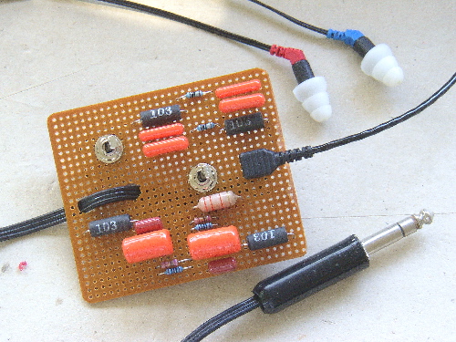
Reference earphones
I think measurement mic is in there somewhere. Of course, now with DSP and convolution as Byrtt has shown us, we can do this from the easy chair with Jriver.
Reference earphones
I think measurement mic is in there somewhere. Of course, now with DSP and convolution as Byrtt has shown us, we can do this from the easy chair with Jriver.
About OB-1 stock sound its much too hot and warm in lows for me, but with post 916 correction curve that transform to Harman curve their performance raise to sky-high in my eyes, also PCA seems happy to feed them
Hey BYRTT - I agree 100%. Cannot listen to my OB-1's without that EQ correction.
BYRTT,
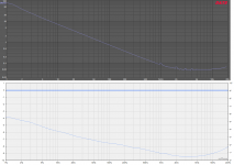
I have been learning a lot from your recent posts. Up to this point I had never really thought about group delay effects when sizing caps. Am I understanding correctly that output impedance determines a given frequency's phase shift, so that a falling impedance curve in the audible band (like you show in your graphs) delays bass frequencies more? Is there an equation for predicting this?
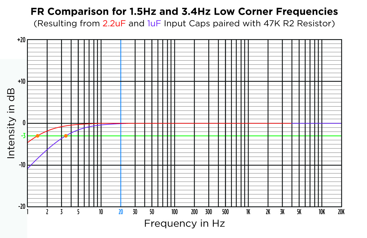
So far I have relied solely on F-3dB = 1 / 2PiRC to size caps, thinking only of amplitude, and trying to get -3db point around 2-3Hz to avoid bass roll off. Maybe there is more to the picture with impedance... Is that why you are using huge input caps with your amp? My thinking was to use the best possible films there for lowest distortion. You can see below that it is pretty easy to get perfect bass extension with a small film when R2 is 47K.
BTW, our amps may be sounding somewhat similar based on your choice of Panny FC. FR series have better ESR, ripple, and lifetime specs, but according to this blind test, FC and FR sound identical! X, how do you like the FR sound?
I have been learning a lot from your recent posts. Up to this point I had never really thought about group delay effects when sizing caps. Am I understanding correctly that output impedance determines a given frequency's phase shift, so that a falling impedance curve in the audible band (like you show in your graphs) delays bass frequencies more? Is there an equation for predicting this?
So far I have relied solely on F-3dB = 1 / 2PiRC to size caps, thinking only of amplitude, and trying to get -3db point around 2-3Hz to avoid bass roll off. Maybe there is more to the picture with impedance... Is that why you are using huge input caps with your amp? My thinking was to use the best possible films there for lowest distortion. You can see below that it is pretty easy to get perfect bass extension with a small film when R2 is 47K.
BTW, our amps may be sounding somewhat similar based on your choice of Panny FC. FR series have better ESR, ripple, and lifetime specs, but according to this blind test, FC and FR sound identical! X, how do you like the FR sound?
Attachments
Last edited:
I think group delay GD at frequency f happens when the frequency response is not linear (a curve). Because mathematically, GD(f) is the derivative (slope) of the FR(f). So the bigger caps push the flat FR further to the left, reducing GD. When you can get GD at 100Hz to be below 0.5mS it's not really audible, and at 20Hz our ears can tolerate several milliseconds. Room reflections are of order 10ms so we are used to it. But when you get it perfect to 1us it's sounds very nice.
I could be wrong reading your layout right there but if you use LM or 78xx regulator there is so much noise to win let reference network get its own remote sence wire as close to load as possible instead of sitting in middle of dirty ground return, below layout should explain the little difference in wiring sheme that pays back very well, also the typical used 0,1uF in feeding rail shall sit as close to regulators input pin as possible.
Wow, thank you BYRTT for spotting this. Yes, you are correct - it is a LM317 based regulator and I have 3 of these circuits in operation. And, yes - currently the ground runs exactly like the blue line in your post #1064. Thank you very much for the recommendation - I will modify my circuit and let you know.
There are so many regulators on this forum, but is there one that you would recommend that is simple and easy to do point-to-point for the PCA?

BYRTT,
I have been learning a lot from your recent posts. Up to this point I had never really thought about group delay effects when sizing caps. Am I understanding correctly that output impedance determines a given frequency's phase shift, so that a falling impedance curve in the audible band (like you show in your graphs) delays bass frequencies more? Is there an equation for predicting this?
So far I have relied solely on F-3dB = 1 / 2PiRC to size caps, thinking only of amplitude, and trying to get -3db point around 2-3Hz to avoid bass roll off. Maybe there is more to the picture with impedance... Is that why you are using huge input caps with your amp? My thinking was to use the best possible films there for lowest distortion. You can see below that it is pretty easy to get perfect bass extension with a small film when R2 is 47K.

BTW, our amps may be sounding somewhat similar based on your choice of Panny FC. FR series have better ESR, ripple, and lifetime specs, but according to this blind test, FC and FR sound identical! X, how do you like the FR sound?
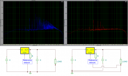
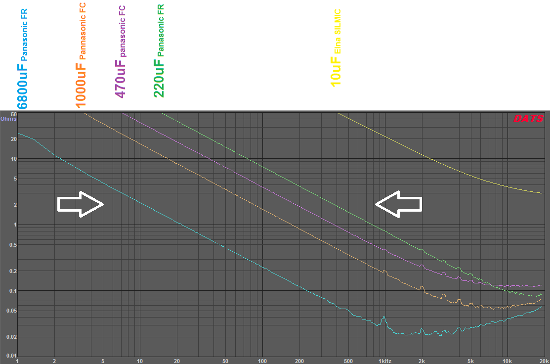
In theory capacitor should be perfect 1st order high pass minimum phase device which means phase lags +90º at DC compared to pass band and at f3 phase lags +45º and this high pass point is dictated by capacitor value. Impedance at lows dictate their electric high pass function and here they perfect device but as impedance go lower the higher the frq they never reach a zero ohms impedance and worst is they not flat out to light speed, they only peak their lowest impedance a short moment (impedance resonance, see the blue 6800uF in curves) and then it raise again because device sadly also behave as inductor which inductance value often is dictated by physical size of capacitor.
What i try with these phase time experiment is not to correct for the natural 1st order 90º lag, correction is very gentle up to 5,2º and try to follow capacitors impedance curve because seen in simulation software that if we zoom into uS/nS area any output device will be little speedier into light loads and a little slower into low impedance.
Agree its right and good enough extension wise to use small film into 47K, because i went whoopee 220uF there was because only 10uF i had laying around was electrolytics and those types have bad distortion figures at low values so therefor upped to 220uF to improve on distortion figure.
Agree our amps probably sound very similar : ) what I probably better like for FC series is their impedance resonance is often more gentle and not so sharp a spike as FR at the cost of a little higher ESR.
Last edited:
Wow, thank you BYRTT for spotting this. Yes, you are correct - it is a LM317 based regulator and I have 3 of these circuits in operation. And, yes - currently the ground runs exactly like the blue line in your post #1064. Thank you very much for the recommendation - I will modify my circuit and let you know.
There are so many regulators on this forum, but is there one that you would recommend that is simple and easy to do point-to-point for the PCA?
Welcome, you right there is so many regulators on forum but i only think they perform as documented if one use their intended PCB layout, therefor think you should be good going with LM317 using point to point layout.
Agree our amps probably sound very similar : ) what I probably better like for FC series is their impedance resonance is often more gentle and not so sharp a spike as FR at the cost of a little higher ESR.
Interesting indeed. I've been watching this caps discussion (which started with Stellarelephant's cap rolling), waiting for some final conclusion before ordering caps for my uber upgrade. What about the FM's - I assume they are something between FC and FR? I've been using the FM's because of the low ESR and somehow they are cheaper than FC's. Maybe for a good reason?
So BYRTT, I don't understand all the technical details, but are you saying that it is better to have the input and output caps of the same series in this case?
Been big is better naughty today : )
Input=220uF and output=2200uF Panasonic FC (no bypass caps at all):
Before using that FC 2200uF at output had a FR 2200uF in there, but it was not good sound probably because its form was so thin in diameter but very long.
After looking at impedance curve for that FC 2200uF thinking was that a few ohms difference will make PCA loading distort group delay as curve looks, maybe not in mS but at least in uS or nS, so based on that curve made a FIR convolution filter that is very mild reverse in timing changing phase only up to about 5,2º without touching amplitude domain at all.
With this capacitor specific filter loaded sound was improved to more natural sound and rhythm, so tomorrow task will be try same light phase change receipt for OB-1 driver units impedance curve : )
Should down the road anybody want to try this filter all it needs is we use same capacitor value and/or brand at output, then i can share convolution file.
I noticed that both Byrtt and X's most recent builds are not using any bypass caps, is that the latest trend that we can all follow?
BYRTT, thanks for the great explanation. I understood most of it! I may audition FC in the future.
Twocents, I think BYRTT said he put an electrolytic on the input only because that's all he had on hand at the moment.
Finally got amp #2 tinned up...and gotta say:
While my first build sounded great, this one knocks my socks off!!!
Twocents, I think BYRTT said he put an electrolytic on the input only because that's all he had on hand at the moment.
Finally got amp #2 tinned up...and gotta say:
While my first build sounded great, this one knocks my socks off!!!
Attachments

Last edited:
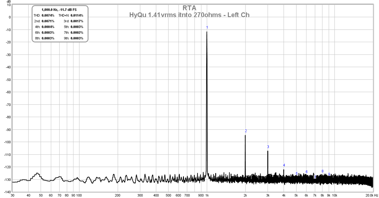
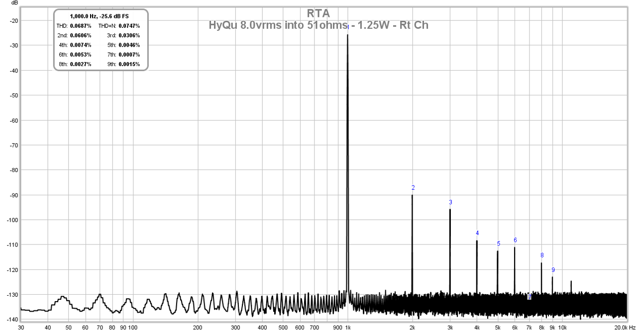
Latest tweaking and tuning the HyQu has resulted in this: can drive 51ohms to 8vrms (1.25 Watts) with a harmonic profile resembling a SE Class A amp. At 1.41vrms into 270ohm load it looks like the most amazing SE Class A amp. All the while only burning off about 3w of Class AB heat per channel.
Here is 1.41vrms into 270ohms:
This is 1250mW into 51ohms for max power output:
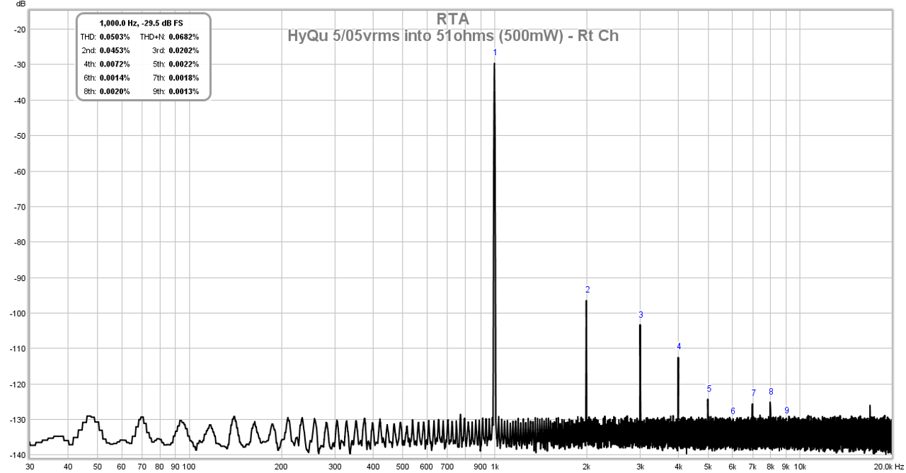
Driving 5.05vrms into 51ohms and sStill able to be fully Class A up to 500mW into 51ohms:
Sound is simply jaw-dropping - perhaps the best I have ever heard, and able to drive even 16ohm cans with ease. Vert very nice sound.
Here is 1.41vrms into 270ohms:
This is 1250mW into 51ohms for max power output:
Driving 5.05vrms into 51ohms and sStill able to be fully Class A up to 500mW into 51ohms:
Sound is simply jaw-dropping - perhaps the best I have ever heard, and able to drive even 16ohm cans with ease. Vert very nice sound.
Attachments

Last edited:
- Home
- Group Buys
- xrk971 Pocket Class A Headamp GB