The sound is very clear, almost to point of being "dry". I will tune the resistor values a bit still as this is the "First Sound" test. The transients an headroom dynamics are very powerful given the much higher bias and higher voltage rail. The resolution of the sound is very high. I will let the components burn in a little more and need to increase the heatsinking as the current ones are woefully undersized so IRF610's probably running too hot - which might affect the sound. It's very promising though and the DC values were close to predictions from LTSpice model. Some work needs to be done on the powersupply to get the broad white noise from the DC step up below 100Hz down.
In general, a very powerrful sounding amp with great sense of "speed". I think use of 1000uF 16v low ESR OSSCON output cap (it fits the space for the Pocket Amp) and 10uF 63v electrolytic input cap (bypassed with 0.1uF 100v film caps) really improves the low corner of the bass response. Measured frequency response shows -0.4dB at 10Hz so essentially almost no bass falloff within audible and sub-audible region.

The new caps might be an interesting upgrade on a "super bass" version of the pocket amp.")
In general, a very powerrful sounding amp with great sense of "speed". I think use of 1000uF 16v low ESR OSSCON output cap (it fits the space for the Pocket Amp) and 10uF 63v electrolytic input cap (bypassed with 0.1uF 100v film caps) really improves the low corner of the bass response. Measured frequency response shows -0.4dB at 10Hz so essentially almost no bass falloff within audible and sub-audible region.
The new caps might be an interesting upgrade on a "super bass" version of the pocket amp.
Attachments
Last edited:
GB 1 update
pcgab - 2 boards - SHIPMENT RECEIVED
zman01 - 1 board - RECEIVED
stellarelephant - 2 boards - SHIPMENT RECEIVED
samoloko - 1 pcb
Morde - 2 board - SHIPMENT RECEIVED
cyteen - 2 boards
funch - 2 boards - SHIPMENT RECEIVED
syyma - 2 boards - SHIPMENT RECEIVED
av-trouvaille - 2 boards - SHIPMENT RECEIVED
Mituisho - 2 boards - RECEIVED
bogde - 2 boards - SHIPMENT RECEIVED
faltinsen - 2 boards
vanofmonks - 1 board - RECEIVED
M_Balou - 2 boards - SHIPMENT RECEIVED
dwpeterson - 2 boards - SHIPMENT RECEIVED
agdr - 1 board
walangalam - 2 boards SHIPMENT RECEIVED
gwrskien - 2 boards - SHIPMENT RECEIVED
redarc12- 2 boards
dw1narso - 2 boards - Received
zimmer64 - 2 boards
shambala - 2 boards - SHIPMENT RECEIVED
HaroldHill - 2 boards - SHIPMENT RECEIVED
gig - 2 boards - Received
hui13 - 2 boards - SHIPMENT RECEIVED
pranavkr -1 board - SHIPMENT RECEIVED
JimS- 1 board
Kumori - 1 board
tubediy - 1 board
AKSA - 1 board - RECEIVED
Last edited:
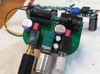
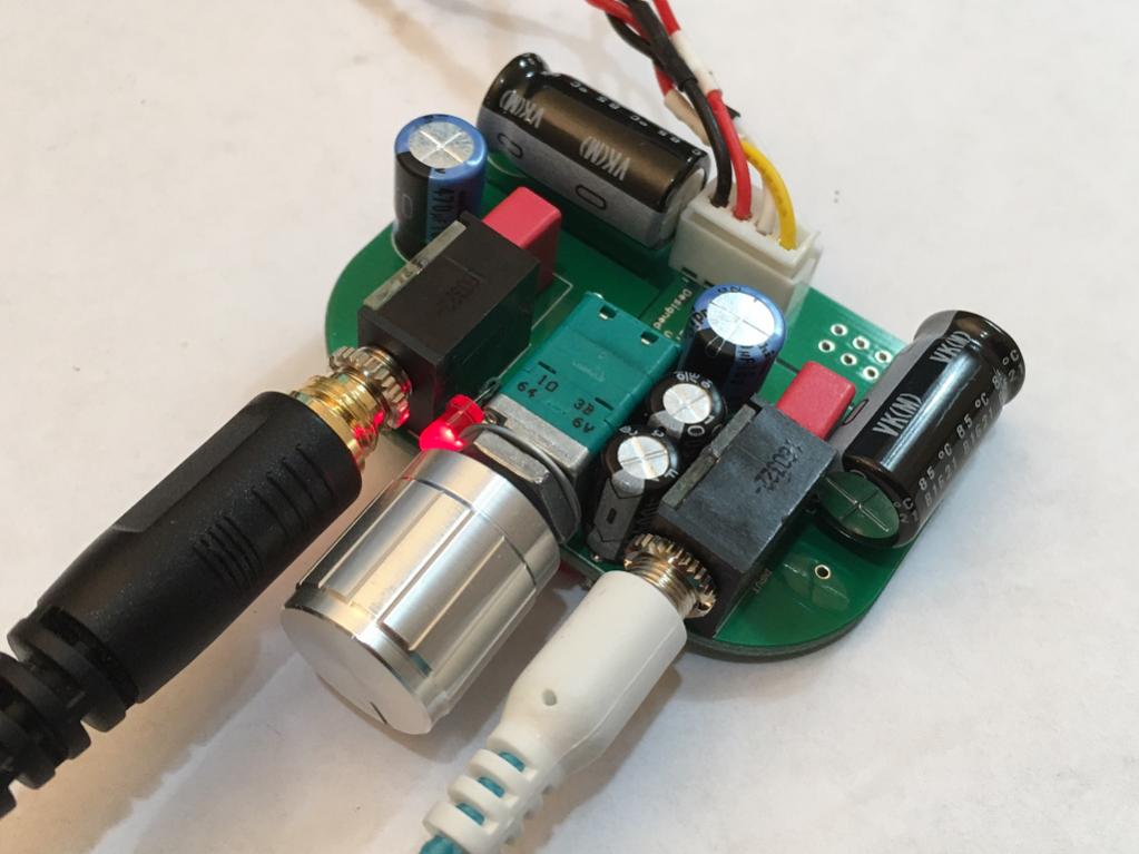
The sound is very clear, almost to point of being "dry". I will tune the resistor values a bit still as this is the "First Sound" test. The transients an headroom dynamics are very powerful given the much higher bias and higher voltage rail. The resolution of the sound is very high. I will let the components burn in a little more and need to increase the heatsinking as the current ones are woefully undersized so IRF610's probably running too hot - which might affect the sound. It's very promising though and the DC values were close to predictions from LTSpice model. Some work needs to be done on the powersupply to get the broad white noise from the DC step up below 100Hz down.
In general, a very powerrful sounding amp with great sense of "speed". I think use of 1000uF 16v low ESR OSSCON output cap (it fits the space for the Pocket Amp) and 10uF 63v electrolytic input cap (bypassed with 0.1uF 100v film caps) really improves the low corner of the bass response. Measured frequency response shows -0.4dB at 10Hz so essentially almost no bass falloff within audible and sub-audible region.
The new caps might be an interesting upgrade on a "super bass" version of the pocket amp.
This setup looks sweet!
I thought the bass sounded deep, full, and effortless when I tried those 1000uF OSCONs on my board. Even my Apple earpods had awesome bass with them, like far beyond what a I thought they were even capable of. I still favor the Nichicons AKs for the extra detail they let come through. The OSCONs have the advantage of compactness though.
What benefit are you aiming to get from larger value electrolytic input caps with the tiny value bypass? Trying to learn.
I was really surprised that I was able to hear differences between caps and it has really piqued my interest in exploring the different options that could fit inside the Altoids tin. I've been trying to learn from other threads and web articles more about the different types of caps used for audio, whether to add a bypass cap and how to size those, effects on FR and impedance anomalies etc. As a newcomer it seems pretty dense, plus there are a lot of different opinions.
I measured my mint tins yesterday. I have a couple brands but they are very similarly sized. I was surprised that they are deeper than I thought. One is 20.5mm deep and the other 21mm. My revelation: The PCB itself plus the mounted SMT side components measure just 3mm thick. That leaves up to 17 or even 18mm of vertical space for caps on the through hole side! So that opens up some options...16 mm caps could be mounted vertically. Or alternatively larger film bypass caps like you stuck on the SMT side for your desktop build could even be used in the tin, if leads were bent to lay them sideways.
On the desktop amp, the one local feedback resistor is 22k and technically I would need 4.7uF film cap to keep the bass extension the same in the input side. Since I don't have any 4.7uF film caps on hand plus they won't fit in the slot. So I decided to use a 10uF electrolytic (put +ve facing in as bias is coming from feedback resistor). Then use a small 0.1uF film bypass to ensure sharp and clear highs. It sounds pretty good actually. I agree that those 1000uF oscons have some deep bass. My measurement show hardly any falloff maybe -0.4dB st 10Hz. I tried my half broken 60ohm Sony MDRV6's and can really feel the difference the higher bias and bigger "desktop" amp's effect on lower impednzxe headphones.
Good luck fitting it into a tin - it's a very different operational feel once boxed since you can hold t in your hand or take it with you. Nice to be free from a desk when using Class A.
Good luck fitting it into a tin - it's a very different operational feel once boxed since you can hold t in your hand or take it with you. Nice to be free from a desk when using Class A.
On the desktop amp, the one local feedback resistor is 22k and technically I would need 4.7uF film cap to keep the bass extension the same in the input side. Since I don't have any 4.7uF film caps on hand plus they won't fit in the slot. So I decided to use a 10uF electrolytic (put +ve facing in as bias is coming from feedback resistor). Then use a small 0.1uF film bypass to ensure sharp and clear highs.
I see. Are you using that same equation fC=1/(2πRC)? For your desktop amp, if R is 22k, and C is 4.7uF (minimum), that puts corner frequency right below 2Hz, which is perfect according to these guys. https://www.v-cap.com/coupling-capacitor-calculator.php.
Which is the local feedback resistor in the pocket version? Trying to figure out how deep the 2.2uF input cap digs.
I like the way you paralleled two caps through one hole (one on each side of the board). Did you have to drill the hole bigger in the board to squeeze another set of leads through there? Or are the bypass cap leads just tacked onto the surface with solder?
I found a PPS cap that be easily substituted in for the 1uF polyester bypass in its original spot at 7.2x7.2x13mm. They have awesome specs. Has anybody heard them before?
Final question: I know two caps in parallel sum in capacitance. Is corner frequency for the circuit then calculated from that sum, or is it just calculated off of the larger of the two caps used?
Yes, that's the equation and the 22k is the local feedback cap. The 2Hz bottom is what I was aiming for as you want to be a two octaves below where you really want the response to get to. It's parallel so the total value is used. I only used 0.1uF so that doesn't affect the overall value of 10.1uF very much. And I just soldered the smaller one into the protruding legs of the bigger one.
Thanks! Sorry to go hijacking your thread with such basic questions about things most folks here probably take for granted! What can I say...I studied art in college! Still wondering:
1) What is the value of the local feedback resistor(s) in the pocket version?
2) With paralleled caps, is overall corner frequency calculated using the summed capacitance?
I forgot to link to that 1uF PPS cap I mentioned.
http://www.mouser.com/ProductDetail...1cc3ydrPrF8759ibQoZNRUNfDaYdMVNpgdIGbcknsAg==
Anybody heard these? Like 'em?
I feel like this guy lol
An externally hosted image should be here but it was not working when we last tested it.
I think I said that the total parallel value of the combo caps is used in calculating the corner frequency. I am not sure what value the PPS cap has over the MKS ones? They cost 3x more. I guess if you hear a difference then go for it. We are getting into the slippery slope of boutique capacitors. There are $4000 1uF caps made of gold film and esoteric dielectrics like Himalayan Yak oil with lambs skin. I'm sure some people think they can hear a difference. In all seriousness, there probably are differences in the $1 vs $10 price range. But probably not much more. You probably won't get much better than a polyethylene audio grade cap but they are huge. We are trying to keep it pocket sized.
If using in a larger desktop case, maybe these might be worth a try? Reviewers seem to love them. For $20ea you better like them
Audiocap PPT Theta 2.0uF 200V Film/Foil Capacitor
If using in a larger desktop case, maybe these might be worth a try? Reviewers seem to love them. For $20ea you better like them
Audiocap PPT Theta 2.0uF 200V Film/Foil Capacitor
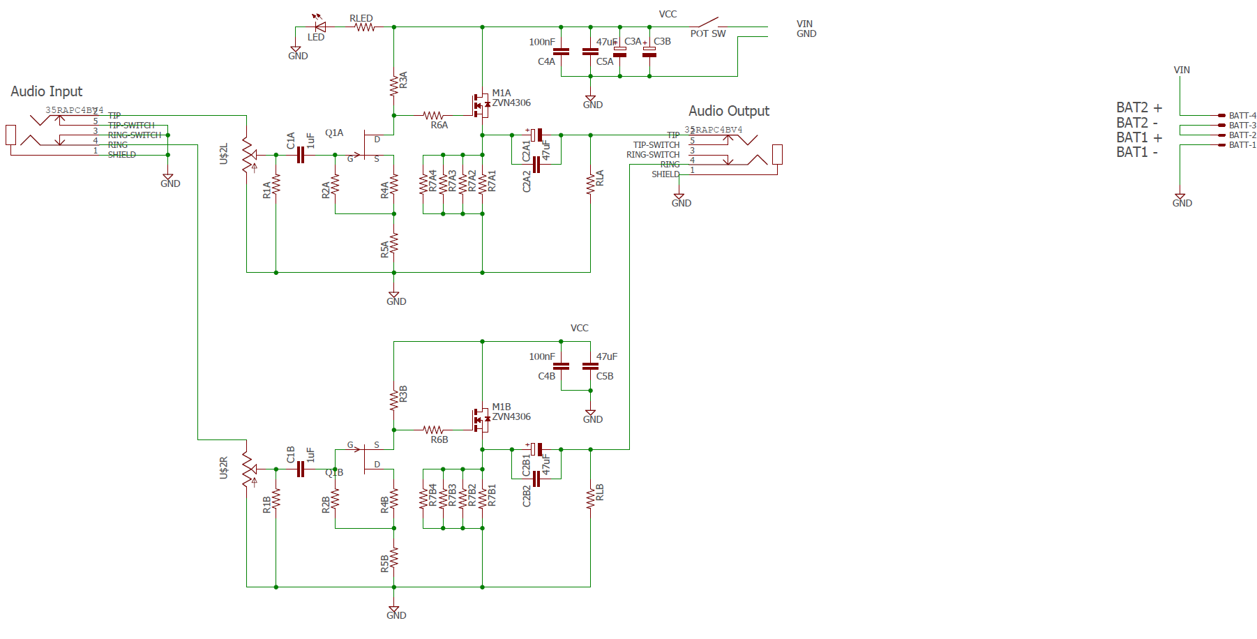
The local feedback resistor, R2 provides self-biasing for the input cap C1 (keeping it from going through a zero crossing - sort of like keeping it in the Class A region as long as input signals are below 1.1v). For the pocket amp, R2 is 47k, and for the desktop version it is 22k. The output cap is of course, biased by the Source pin of the MOSFET at about 7v so should stay in crossoverless region all the time.
You need to see these caps. Don't ask what they cost.
http://duelundaudio.com/cast-capacitor/
http://www.mundorf.com/en/?category=hifi&menu=caps_audio&content=mcap_supreme_evo_silvergold_oil
You need to see these caps. Don't ask what they cost.
http://duelundaudio.com/cast-capacitor/
http://www.mundorf.com/en/?category=hifi&menu=caps_audio&content=mcap_supreme_evo_silvergold_oil
Last edited:
X's personal NHB version
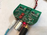
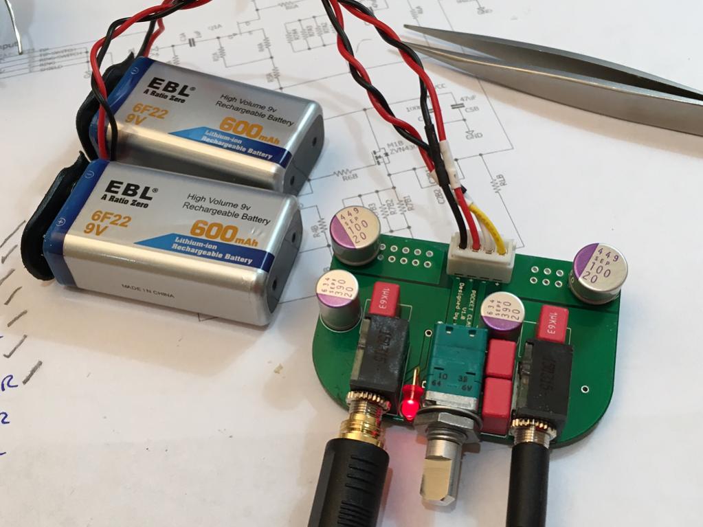
I had some time to build my own personal no holds barred (NHB) amp. I am trying out the Nichicon AK 470uF output caps per StellarElelphant's recommendation, paired with 2.2uF Wima's and on input, 10uF 100v electrolytics paired with 100nF 100v MKT's. I am also using super-matched FETs (matched to 4 significant figures with JFETs selected for 7mA bias and MOSFET running 50mA bias).
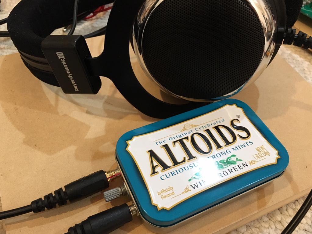
So here it is, doesn't look too different but theoretically, should have deeper bass extension and better highs. Will listen for a few days and report back. Also will put it against a standard on with my AB box.

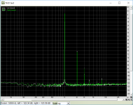
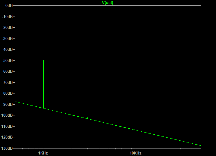
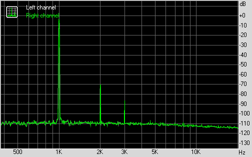
Here is the FFT - mostly H2 with H3 about -30dB less.
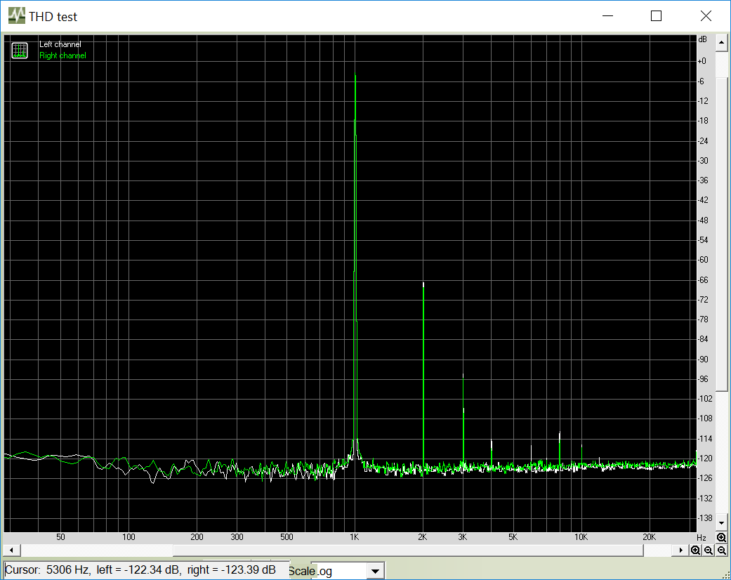
I had some time to build my own personal no holds barred (NHB) amp. I am trying out the Nichicon AK 470uF output caps per StellarElelphant's recommendation, paired with 2.2uF Wima's and on input, 10uF 100v electrolytics paired with 100nF 100v MKT's. I am also using super-matched FETs (matched to 4 significant figures with JFETs selected for 7mA bias and MOSFET running 50mA bias).
So here it is, doesn't look too different but theoretically, should have deeper bass extension and better highs. Will listen for a few days and report back. Also will put it against a standard on with my AB box.
Here is the FFT - mostly H2 with H3 about -30dB less.
Attachments

Last edited:
Initial listening impressions are very good indeed. All tracks so far play with great snap in bass and clear and articulate highs. I tested some tracks with sub 20Hz content and you can feel the pressure waves (Perfect Cicle's Lullaby). 50mA bias on MOSFET and 7mA bias on JFET seems to be a nice setting.
Power Levels and Output Impedance
I finally had some time to run some LTSpice sims to check what is predicted output impedance and max power before clipping.
Output impedance was calculated to be 1.08ohms using a 25ohm load vs no-load case. For 1.00v nominal output, a 25ohm load caused a 43mV drop in output. So 0.043v x 25ohms = 1.08ohms output impedance.
Max power before clipping was calculated by simulations to show that the amp can drive 60ohm cans to a max of 5.32v (p-p) before clipping. This is about 60mW into 60ohms if I did the math right.
For 250ohm cans, it can drive 10v (p-p) before clipping, and this is about 50mW into 250ohms max power. I think pain threshold on my DT880-250's is about 5.5v so I am not power limited by any means.
In both cases, the THD was well below 1% before clipping.
Last edited:
Output impedance was calculated to be 1.08ohms using a 25ohm load vs no-load case. For 1.00v nominal output, a 25ohm load caused a 43mV drop in output. So 0.043v x 25ohms = 1.08ohms output impedance.
I meant to say 1.000v at 25ohms load and 1.043v with no load, so (1.043V-1.000v)/1.000v x 25ohms = 1.08ohms
Now units work out correctly.
GB2 Update
As far as I can tell, all folks who ordered on GB2 have now been shipped. Thanks for participating. More boards still available.
Turbon - 1 board and 2 sets matched FETs - SHIPPED
Schlomoff - 1 built and tested board and 4 SMT populated boards with matched FETs - SHIPPED (OR, USA Address)
pranavkr - 1 board - SHIPPED
Potatowedge - 2 boards and 1 set of matched FETs - SHIPPED
pcgab - 2 boards - SHIPPED
bogde - 4 boards - SHIPPED
adn6244 - 2 boards - SHIPPED
tcpoint - 2 boards - SHIPPED
funch - 2 boards and 2 matched sets of FETs - SHIPPED
Wanfai - 1 board and 1 matched sets of FETs - SHIPPED
883bkong - 2 boards - SHIPPED
Kylej1015 - 2 boards - SHIPPED - RECEIVED
Jammer55 - 4 boards - SHIPPED
Tupam - 2 boards - SHIPPED
aud1out - 2 boards - SHIPPED (MI, USA Address)
tommylck - 2 boards & 2 sets of matched FETs - SHIPPED
slaterlovesspam (Head-Fi.org) - 1 PCB and 1 special parts kit - SHIPPED
As far as I can tell, all folks who ordered on GB2 have now been shipped. Thanks for participating. More boards still available.
XRK971 pocket class Headphone amp
This project started over in this thread:
http://www.diyaudio.com/forums/head...2-based-se-class-headamp-without-heat-14.html
but I thought it would be good for it to have a dedicated GB thread here. It's a superb sounding single ended (SE) Class A topology that has a predominantly a second harmonic distortion profile with just a tad bit third harmonic and not much else. The noise floor is about -125dB and dynamic range is about 96dB with THD measured to be about 0.029% at 1kHz and driving a 270ohm load at 700mV RMS. Note that most of that HD is H2 so the sound is very much like a nicest SE tube amps. Frequency response with a 47uF output coupling cap was measured at -1.5dB at 20Hz and 45kHz (probably limit of measurement as ADC sampling was 96kHz). The sims show that it can go beyond several MHz on the high end. Best part is that it fits in an Altoids tin and looks like a CMOY headamp - but it's no op amp. It relies on just two FETs. The ever popular BF862 JFET for the input and a ZVN4306 MOSFET for the output stage. The bias runs between 50mA and 60mA which allows it to last about 4 to 5 hours on a pair of 600mAhr Li-ion rechargeable 9v batteries. The amp dissipates about 2w so never gets hot but makes a nice hand warmer for your pocket in the winter.
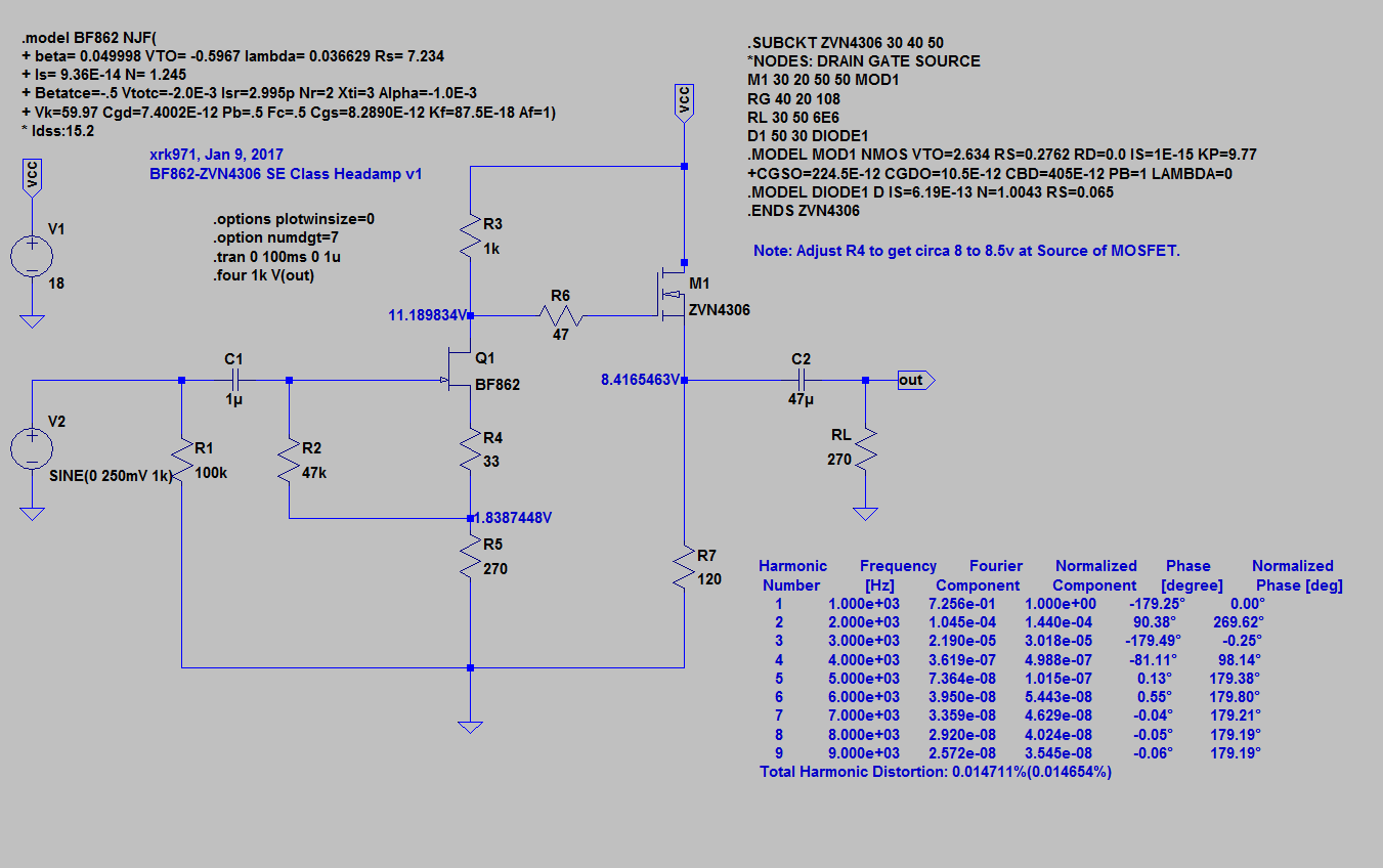
This is the basic circuit - very simple and it's what gives it a natural and very musical sound that is engaging, lively, never sterile.
Here is the predicted HD profile:
Here is what the hand made prototype looks like:
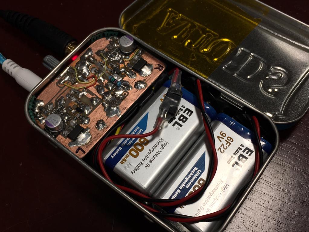
You can listen to this amp as recorded with UCA202 connected to a 270ohm load resistor. Change the file name extension from .asc to .mp3 to listen.
http://www.diyaudio.com/forums/atta...wo-transistors-clapping-pocket-class-clip.asc
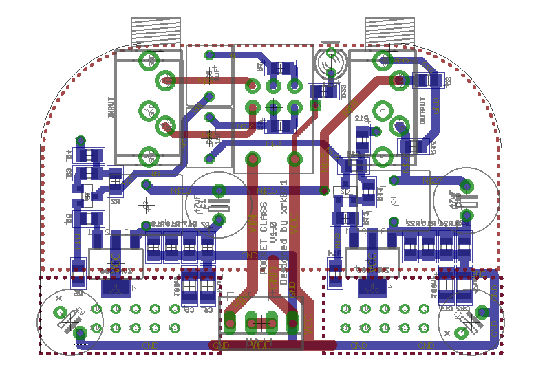
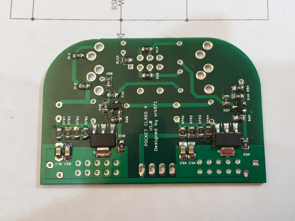
This is the layout for the actual board being sold for this GB:
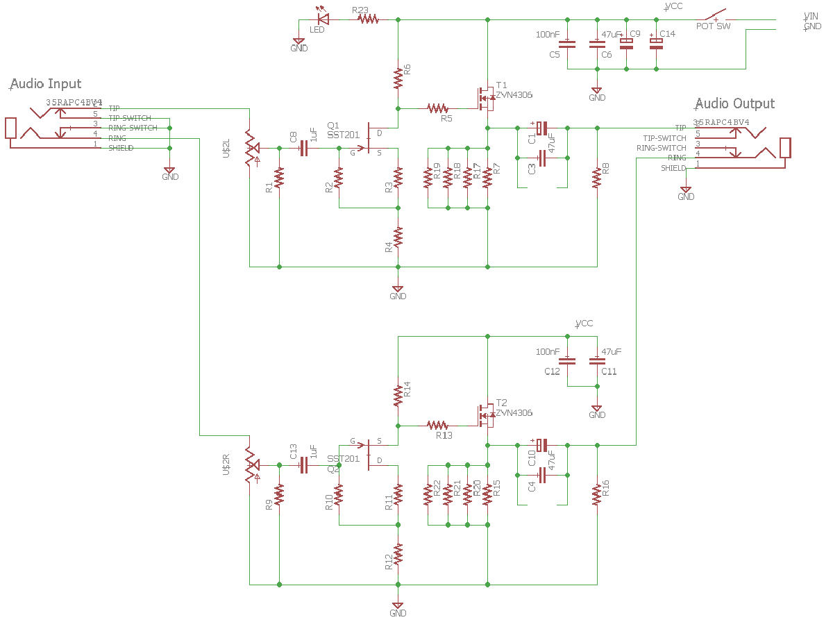
This is the associated schematic that goes with this layout:
Many thanks to BabyDontHertzMe (BDHM) for making the layout and to Agdr for providing the initial Altoids footprint Eagle file.
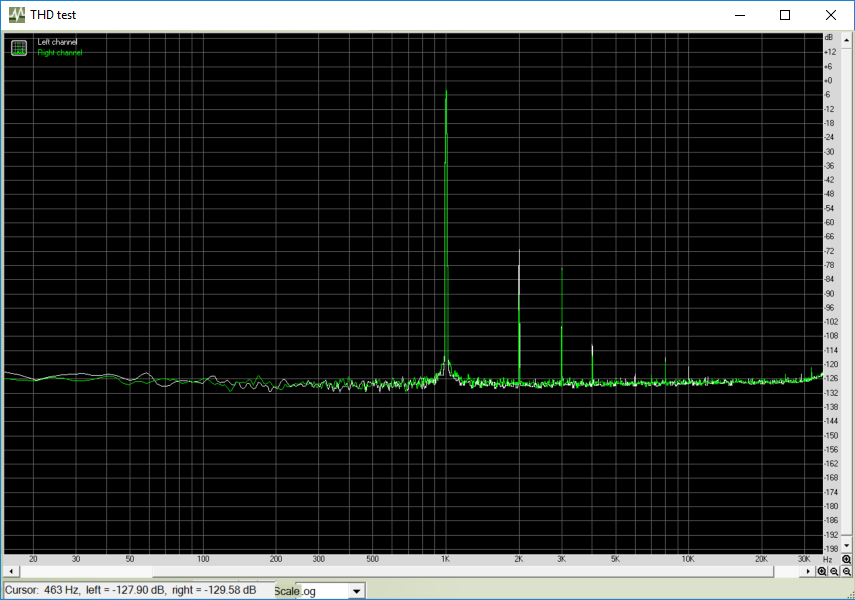
Here is the measured HD using Focusrite Solo 2nd gen at 96kHz and 24bit:
The HD measured using a UCA202 at 16bits and 48kHz looks like this:
Edit Feb. 18, 2017 - Here is the latest measured frequency response and THD from the GB PCB:

Edit Feb. 18, 2017 - Here is the latest measured FFT from the GB PCB measured for 1kHz excitation at 700mV into a 270ohm load:

This headamp can drive headphones with impedances as low as 30ohms no problem. The GB has already started in the other thread and is currently at 6 people and 11 boards. We have enough critical mass but I want to keep it open a bit longer to make sure everyone who wants one gets to place an order.
The pricing is $12 for one board in continental US (CONUS) and $17 for outside of CONUS. For two boards add $5. Price includes shipping.
Price for 1 set of matched FETs is $17 shipping included in US, $20 elsewhere.
Edit Mar 8, 2017: international orders please add $1 for extra PayPal fees for 2 board and under. Will be more for larger orders (about +1%).
Price for board with matched FETs installed is $39ea (shipping not included).
Price for board with matched FETs and all SMT parts installed is $80ea (shipping not included).
Price for a fully-populated and tested amp board (with matched FETs) is $200 (includes shipping in CONUS). More info here.
Please use the quote feature to add your name and desired number of boards to grow the list:
Drpro -1 board and one set of match FETs
Latest BOM is post 15:
http://www.diyaudio.com/forums/group-buys/302859-xrk971-pocket-class-headamp-gb-2.html#post4967657
BOM errata for C9 and C11:
http://www.diyaudio.com/forums/group-buys/302859-xrk971-pocket-class-headamp-gb-4.html#post4971339
Edit - Jan 9, 2017: The GB PCB works! Sounds fantastic.
Final as-built schematic:
Final as-built BOM:

Here is the template for drilling the holes in the mint tin, courtesy of Agdr (same pattern as his Super CMOY 1688 as the pot, LED, and 3.5mm jack locations are the same).
http://www.diyaudio.com/forums/group-buys/302859-xrk971-pocket-class-headamp-gb-12.html#post4985588
GB2 Update
Drpro - 1-board and 1- set matched FETs
As far as I can tell, all folks who ordered on GB2 have now been shipped. Thanks for participating. More boards still available.
- Home
- Group Buys
- xrk971 Pocket Class A Headamp GB