On the end of the PCB that contains the output jack I measured the voltage between ground and the mosfet source pin (pin 1 in the datasheet) and it was 0.48v. Then it started dropping and I noticed that C3 on that end was getting very hot. It actually gave me a small 2nd degree burn so we're not talking about normal Class A amp hot. On the other end of the PCB the mosfet source pin measures a stable 0.58v and C3 stays cool. This is with NiMh batteries which measure 9.1v and 8.45v (same brand so not sure why the disparity).
And still no sound from the output after it going silent in earlier testing. On headphones I can hear a little click-thump when the switch is turned on but no music comes through.
And still no sound from the output after it going silent in earlier testing. On headphones I can hear a little click-thump when the switch is turned on but no music comes through.
The mosfet pins are GDS left to right 1,2,3 so Source is pin 3, same as what leads to the resistor array. It should be around 6v to 8v if your amp is working right.
Pin 2 should be drain and same as Vcc or about 16v for two 8v batteries in series.
If you are only measuring 0.48v at pin 3, the only thing that can cause this is a short somewhere from the source to ground, which is basically why the mosfet is very hot. Or the mosfet is fried from ESD. You can check this by removing batteries and testing the resistance between the D and S pins. It should be in the tens of kOhms. Not single digit ohms. If low - mosfet has failed in shorted condition.

Are your DC setpoints close to schematic below? Are you using BF862 or 2SK209 JFETs? Are you using genuine BF862’s?

Pin 2 should be drain and same as Vcc or about 16v for two 8v batteries in series.
If you are only measuring 0.48v at pin 3, the only thing that can cause this is a short somewhere from the source to ground, which is basically why the mosfet is very hot. Or the mosfet is fried from ESD. You can check this by removing batteries and testing the resistance between the D and S pins. It should be in the tens of kOhms. Not single digit ohms. If low - mosfet has failed in shorted condition.
Are your DC setpoints close to schematic below? Are you using BF862 or 2SK209 JFETs? Are you using genuine BF862’s?
Last edited:
Thanks for taking the time to help! The problem was I had one of the 2200uF rail caps in reverse polarity. I can't believe I did that. I've built an M2x with your SLB power supply and soft-start and never made such a rookie mistake. 
Sadly that error fried the cap. So I pulled out the other 2200uF rail cap (C3) and temporarily replaced both with 10uFs (the largest I could find in my stash). It's making music again although I assume the sound will improve when I get big caps back in there.
After the rail caps repair I checked the mosfets again. Turns out I was looking at the wrong ones! I thought you meant the 2SK209-GR; checking the ZVN4306GTA I get ~15v on pin 2 (I assume it's a bit low due to somewhat old NiMH 9v batteries) and ~6.6v on pin 3. Seems okay.
Last edited:
Glad you found the problem. A hot cap usually is backwards and lucky it did not explode. The 2SK209 is a JFET - so it did not make sense when you said Source was pin 1. An N channel JFET is totally different than an N channel enhancement mode MOSFET. The JFET is conducting between S and D with no gate voltage. In fact, it acts like a variable resistor and S and D can be reversed.
The rail cap will give you better stereo separation. It will work with 10uF but stereo image will not be very good.
Thanks for debugging. Hope you enjoy the amp now.
The rail cap will give you better stereo separation. It will work with 10uF but stereo image will not be very good.
Thanks for debugging. Hope you enjoy the amp now.
Glad you found the problem. A hot cap usually is backwards and lucky it did not explode. The 2SK209 is a JFET - so it did not make sense when you said Source was pin 1. An N channel JFET is totally different than an N channel enhancement mode MOSFET. The JFET is conducting between S and D with no gate voltage. In fact, it acts like a variable resistor and S and D can be reversed.
The rail cap will give you better stereo separation. It will work with 10uF but stereo image will not be very good.
Thanks for debugging. Hope you enjoy the amp now.
I did some listening this morning with my iPhone 13 driving the headphones directly vs. going through the PCA (with 10uF rail caps, running on 9v alkalines). The PCA has gain, as expected, and what seems to be a little more 'oomf' in the low frequencies. I think it's an improvement over the iPhone alone but I'm also struck by how capable the iPhone is; it can drive the headphones quite well with excellent SQ. Still, I'm looking forward to more listening to the PCA with the larger rail caps. BTW I didn't find the stereo separation to suffer much, if at all, with the smaller 10uF caps. Maybe that's just my lack of hearing acuity.
Re: the mosfets, I bow to your electronics knowledge. I was fooled by the fact that both Digi-Key pages for the 2SK209-GR and ZVN4306GTA have:
| FET Type | N-Channel | |
| Technology | MOSFET (Metal Oxide) |
Anyway the fact that I was checking the ZVN4306GTA explains why I was seeing odd voltages and also why the voltages on a couple of the pins were swapped on one channel vs. the other.
Last edited:
The iPhone Lightning plug dongle is your comparison? They do work amazingly well for lower impedance phones. If you have something like 250ohm Beyer DT880's, a proper headphone amp makes all the difference as it can driver higher voltages. If you want to experience the same sound signature of the pocket Class A with a lower impedance phone, the desktop Class A (DCA) is better - uses 120mA bias current and can handle 32ohm loads.
Same simple design but with built in low ripple cap multiplier PSU and uses TO220 MOSFET (like IRF610).
https://www.diyaudio.com/community/threads/xrk971-desktop-class-a-dca-headphone-amp.322638/


The above is a simple amp and sounds great.
If you want to drive low impedance headphones (even 8ohm ones to several W), I made a parallel OPA1622 headphone amp that can drive 8ohm speakers.

I'm testing it here with a DC protect circuit using SSR's and an ultra low noise PSU:

Not Class A anymore but fun stuff. Sounds really powerful and CLEAN. Here is FFT for 51ohm load and 1Vpp:

Same simple design but with built in low ripple cap multiplier PSU and uses TO220 MOSFET (like IRF610).
https://www.diyaudio.com/community/threads/xrk971-desktop-class-a-dca-headphone-amp.322638/
The above is a simple amp and sounds great.
If you want to drive low impedance headphones (even 8ohm ones to several W), I made a parallel OPA1622 headphone amp that can drive 8ohm speakers.
I'm testing it here with a DC protect circuit using SSR's and an ultra low noise PSU:
Not Class A anymore but fun stuff. Sounds really powerful and CLEAN. Here is FFT for 51ohm load and 1Vpp:
Last edited:
I know, using an iPhone with the Lightning adapter isn't a real audiophile test. Still, it's no slouch
My phones are 48R/100dB which the PCA should handle, correct? With those specs they should be pretty easy to drive? I'll see how I end up using the PCA; if it's just at my desk while working I'll seriously consider building the desktop version (or maybe the LuFo HPA).
Now I'm listening to the PCA being fed by the audio output from my Dell laptop's dock and it sounds very good. Hard to do A/B testing without accurate level matching but I think the PCA is adding some spice and sparkle.
BTW, is there any way to reduce the thump at switch on? And would replacing the Ali Express sourced potentiometer with a real Alps or Bourns version do anything for SQ?
Turn on thump is eliminated if you add a cap multiplier circuit which has a slow ramp up. So the DCA solves that problem. You can make the small little one for PCA discussed earlier designed by RaptorLightning and that will solve it as well. Also, the SSR DC protect circuit has a delay turn on that prevents thump as well. These are all going to add complicity and size it a very small compact circuit. It’s just easier to disconnect the phones before powering up to keep it simple.
48ohms is on the low side for 60mA bias current if you like to play loud or have lots of dynamic range.
Let’s say you want 12dB of headroom on top of nominal 1mW at 90dB. 12dB is 4x3dB (3dB is doubling). That’s 16mW needed.
Sqrt(0.016W x 48ohms)=0.88Vrms=2.5Vpp
V=IR solve for I=V/R=2.5V/48ohms=52mA peak current.
So if you keep bias current at least 52mA you are ok and not current limited. But if you play at levels higher than 1mW and dynamic peaks exceed 12dB, it will distort or clip.
If your headphones are 100dB sensitive - you are probably fine if you listen at 90dB (and that’s loud).
Last edited:
Can you give me pointers for measuring the bias current, if that's possible?
I just found some Wima 1.0uF (and 2.2uF) caps that I had stashed for a second SLB build! Where should they go on the SMD side of the PCA, across C2_1 or C2_2? I have 1000uF 16v OSCON on the top side C2_1 and C2_2 spots.

I just found some Wima 1.0uF (and 2.2uF) caps that I had stashed for a second SLB build! Where should they go on the SMD side of the PCA, across C2_1 or C2_2? I have 1000uF 16v OSCON on the top side C2_1 and C2_2 spots.
Last edited:
Measure voltage across the resistor array (which is same as voltage of mosfet source pin 3). Use ohms law I=V/R. R is 470ohns/4 or 117.5ohms. For say 7.5v across resistors or source pin is 7.5v/117.5 = 64mA.
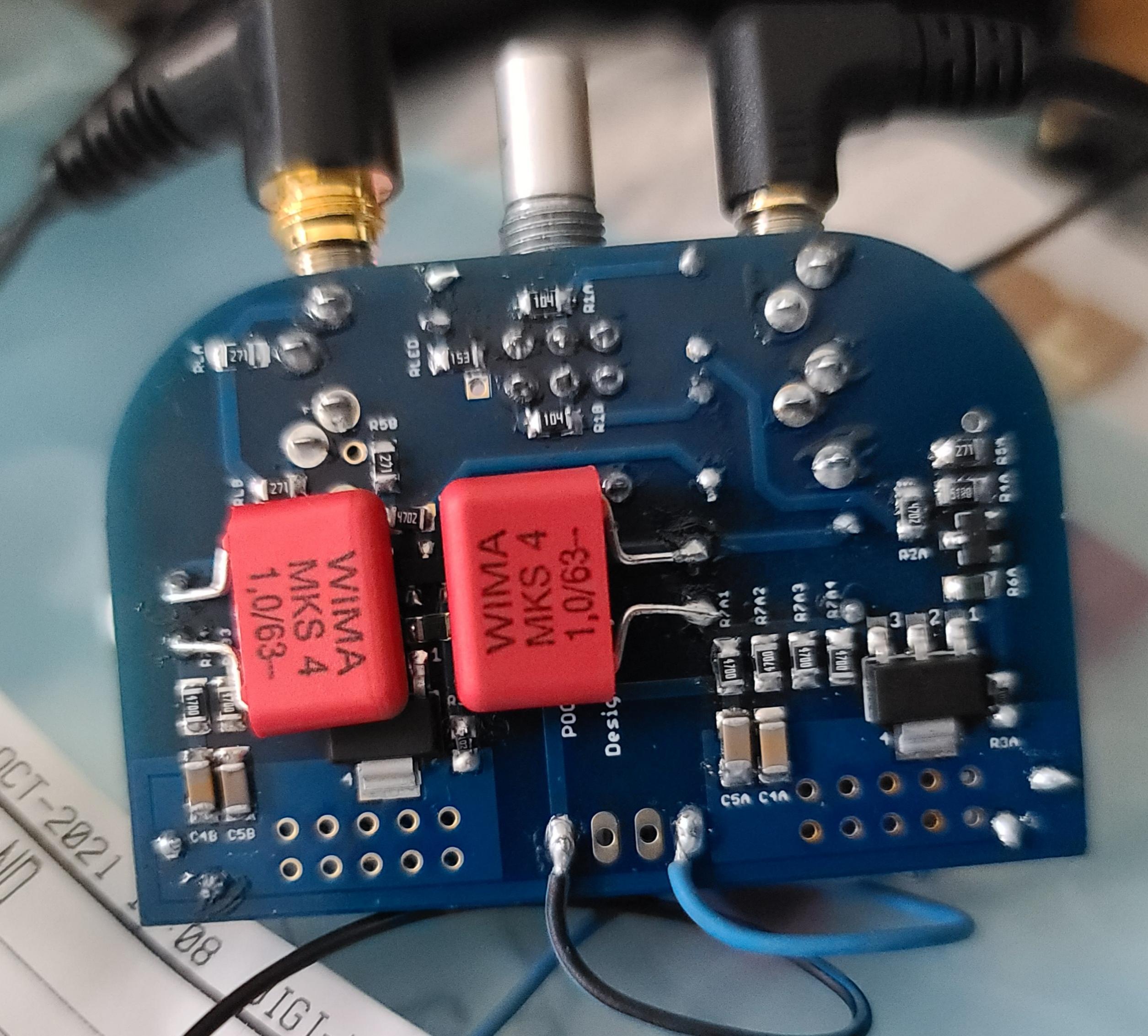
Bypass film caps go across output caps C1 and C10. I have soldered them to the legs sticking out of the SMT side.

An example is by noobman earlier in thread:
Bypass film caps go across output caps C1 and C10. I have soldered them to the legs sticking out of the SMT side.
An example is by noobman earlier in thread:
Thanks. I measure 5.5v and 5.6v across the resistor arrays for the two channels. So ~48ma. However, my alkaline 9v batteries are down to 8.4v and 7.9v.
I'm looking at the PCB itself which has different identifiers for the components. So if I'm understanding correctly what you called C1 is marked as C2A1 and C10 is C2B1 on the PCB.

I'm looking at the PCB itself which has different identifiers for the components. So if I'm understanding correctly what you called C1 is marked as C2A1 and C10 is C2B1 on the PCB.
Last edited:
Since I'm going to be using my PCA exclusively while sitting at my desk I'd like to power it with USB instead of batteries. Searching through this thread it seems that a MT3608 DC step up board would work. Does that need additional filtration or will it be low enough noise to use as-is?
I have used the same thing but be aware that you can’t drive the PCA directly with it since the amp presents such a high current load that the DCDC boost shuts down upon startup. You will need to send it through a cap multiplier to have a slow ramp up soft start. Also, these units have a tiny IC that does the high current switching and are prone to exploding into a bright fireball if you adjust the voltage too fast and the current spikes. They are fragile during adjustment. Once set and working they seem fine. But I have lost more than a dozen in a bright supernova during initial adjustment period.
If desktop use and you plan on putting it in a larger chassis, use a bigger DCDC unit.
Or use a 19v laptop supply and 3 diodes in series to drop it by 1.8v.
One of the lowest noise circuits that combines a cap Mx and a voltage regulator and CLC filter is my simple regulated cap Mx board. It’s going to provide a slow ramp, low ripple and low noise PSU for smaller projects like this. Use a 24v SMPS wall wart or Class 2 linear wall supply and feed the cap Mx for 4 drop to 20v then a regulator down to 16.5v to 17v.
https://www.etsy.com/listing/707414288/simple-cap-mx-regulated-power-supply?click_key=4cca0122e26708f3e31593412f434ec71857ef61:707414288&click_sum=e12b16ec&ref=shop_home_recs_19
I have used the same thing but be aware that you can’t drive the PCA directly with it since the amp presents such a high current load that the DCDC boost shuts down upon startup. You will need to send it through a cap multiplier to have a slow ramp up soft start. Also, these units have a tiny IC that does the high current switching and are prone to exploding into a bright fireball if you adjust the voltage too fast and the current spikes. They are fragile during adjustment. Once set and working they seem fine. But I have lost more than a dozen in a bright supernova during initial adjustment period.
If desktop use and you plan on putting it in a larger chassis, use a bigger DCDC unit.
Or use a 19v laptop supply and 3 diodes in series to drop it by 1.8v.
One of the lowest noise circuits that combines a cap Mx and a voltage regulator and CLC filter is my simple regulated cap Mx board. It’s going to provide a slow ramp, low ripple and low noise PSU for smaller projects like this. Use a 24v SMPS wall wart or Class 2 linear wall supply and feed the cap Mx for 4 drop to 20v then a regulator down to 16.5v to 17v.
https://www.etsy.com/listing/707414288/simple-cap-mx-regulated-power-supply?click_key=4cca0122e26708f3e31593412f434ec71857ef61:707414288&click_sum=e12b16ec&ref=shop_home_recs_19
Your regulated cap Mx board looks great but I like the laptop power supply option since I already have several. What current rating would I need for the diodes?
Basic 1A axial 1n400x is fine as amp only needs 150mA max for both channels.
If using only laptop SMPS, try several - some are quieter than others. I have found laptop supplies by HP or Dell are generally quieter than no name brands. Add 1000uF / >100uH (with 50ohm in parallel with inductor) / 1000uF between the laptop supply and the amp works well to catch any amps noise.
If using only laptop SMPS, try several - some are quieter than others. I have found laptop supplies by HP or Dell are generally quieter than no name brands. Add 1000uF / >100uH (with 50ohm in parallel with inductor) / 1000uF between the laptop supply and the amp works well to catch any amps noise.
Basic 1A axial 1n400x is fine as amp only needs 150mA max for both channels.
If using only laptop SMPS, try several - some are quieter than others. I have found laptop supplies by HP or Dell are generally quieter than no name brands. Add 1000uF / >100uH (with 50ohm in parallel with inductor) / 1000uF between the laptop supply and the amp works well to catch any amps noise.
Thanks for the info. I used a Dell 19.5V laptop power supply, 3 * 1n4004 to bring the voltage down (as you suggested), and the PO89ZB inline DC filter for SMPS from the DIYAUDIO store. It worked out great.
- Home
- Group Buys
- xrk971 Pocket Class A Headamp GB