Hi there,
I am a novice and probably asking not the right question but just in case if you know something about the so called "active cards/boards" of LINN - I have three sets installed in my moded LK 100 - three of them. Taking into account LINN designed them long time ago and looking at the crap inside the amps/I had to change any single Rubicon there, the diodes, the PS caps, the power transistors etc./ I presume the active crossovers need some mod but I do not have the knowledge for designing that - I can only try to execute your ideas.
Thanks spending time for that,
Ignat
Hi Ignat - it doesn't really fit on this thread, but if you start one dedicated to this topic and post up schematics, layouts and maybe some board pictures, you might receive some help.
Thanks, as soon as I get some info about the cards will come with it.
Cheers
Almost there ")
Changelog in v4:
+ Reverse diodes on regulator's input-output.
+ Completed the power supply traces.
+ Optimized the thermal relief pads - now thickier and with rotation in some places.
+ Vias are everywhere i've found appropriate to stuck them. And even more!
+ Multiple footprints for small PS caps - (2/2.5mm and 2.5/3.5mm).
+ Holes! Actually four of them - i should withdraw the hole in bottom-right corner (at TS) for better power traces routing. Three is a magic number.
It takes three legs to make a tripod or to make a table stand,
And it takes three wheels to make a vehicle called a tricycle
And every triangle has three corners,
Every triangle has three sides,
No more, no less,
You don't have to guess
That it's three
Can't you see?
It's a magic number.
Fair enough it will hold the board in place, because three - is a magic number.
+ "Proper" power traces for opamps, leaving center point between bypass caps clean of traces - the currents from "+" and "-" should flow thru bypass caps and end-up in single point canceling each other out.
- 3 traces left unrouted i'm unable to fit them nicely - lots of power traces to cross - i should leave them hanging - anyway the board is suited for rearrangement of connections. There will be jumper wires.
- Had to go with smaller component labels on silkscreen - 7mil thick/35mil height. PCB production allows 6mil silkscreen, so i'm on the safe side.
...
Ouch, there is some free space under PSU - i can move it a little to give more space for regulator heatsinks. Too bad i already have the power traces routed No problem, it is doable. In addition, i'll allow 20mm caps to be fitted on the board - currently there is space for 18mm, and 1mm wouldn't hurt.
I can't give "multiple" footprint feature to large PS caps, as i want to keep the rail planes solid.
*gettin sick of this project*
I've got some elna silmics 10uf/25v for opamp's bypassing, heyah! 320 pieces...
Currently the board allows filter caps of 5x20mm (up to 18mm lead spacing).
I've checked WIMA datasheets and they have caps in 6x20mm case - maybe i should change the footprints on the capacity-demanding sections (bafflestep, woofer/global notches and woofer high/low pass).
I have simulated the board in microcap and it works!
So, todo:
- Move PSU
- 20mm diameter footprint for PSU caps
- Check whether it's possible to squeeze 6mm thick caps in woofer filters.
- Simulate the PSU - to find out proper large cap and feeding resistor values.
By the way, the phase shifters could work as shelve filters by changing the ratio of resistors in the feedback. Yay!
Changelog in v4:
+ Reverse diodes on regulator's input-output.
+ Completed the power supply traces.
+ Optimized the thermal relief pads - now thickier and with rotation in some places.
+ Vias are everywhere i've found appropriate to stuck them. And even more!
+ Multiple footprints for small PS caps - (2/2.5mm and 2.5/3.5mm).
+ Holes! Actually four of them - i should withdraw the hole in bottom-right corner (at TS) for better power traces routing. Three is a magic number.
It takes three legs to make a tripod or to make a table stand,
And it takes three wheels to make a vehicle called a tricycle
And every triangle has three corners,
Every triangle has three sides,
No more, no less,
You don't have to guess
That it's three
Can't you see?
It's a magic number.
Fair enough it will hold the board in place, because three - is a magic number.
+ "Proper" power traces for opamps, leaving center point between bypass caps clean of traces - the currents from "+" and "-" should flow thru bypass caps and end-up in single point canceling each other out.
- 3 traces left unrouted
i'm unable to fit them nicely - lots of power traces to cross - i should leave them hanging - anyway the board is suited for rearrangement of connections. There will be jumper wires.- Had to go with smaller component labels on silkscreen - 7mil thick/35mil height. PCB production allows 6mil silkscreen, so i'm on the safe side.
...
Ouch, there is some free space under PSU - i can move it a little to give more space for regulator heatsinks. Too bad i already have the power traces routed
No problem, it is doable. In addition, i'll allow 20mm caps to be fitted on the board - currently there is space for 18mm, and 1mm wouldn't hurt.I can't give "multiple" footprint feature to large PS caps, as i want to keep the rail planes solid.
*gettin sick of this project*
I've got some elna silmics 10uf/25v for opamp's bypassing, heyah! 320 pieces...
Currently the board allows filter caps of 5x20mm (up to 18mm lead spacing).
I've checked WIMA datasheets and they have caps in 6x20mm case - maybe i should change the footprints on the capacity-demanding sections (bafflestep, woofer/global notches and woofer high/low pass).
I have simulated the board in microcap and it works!
So, todo:
- Move PSU
- 20mm diameter footprint for PSU caps
- Check whether it's possible to squeeze 6mm thick caps in woofer filters.
- Simulate the PSU - to find out proper large cap and feeding resistor values.
By the way, the phase shifters could work as shelve filters by changing the ratio of resistors in the feedback. Yay!
Attachments
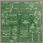
Yay, the PCB has passed the verification and sent to production!
My first PCB... hehe!
You have used lots and lots and lots of SMDs. How are these to be assembled? Do they come pre-assembled? If so, how does one change the crossover frequency, baffle step frequency and depth, and so on?
This board has a lot of functionality crammed in to a very small space it seems. How big is the board footprint?
-Charlie
These boards won't come in kit - almost all of the components should be calculated and changed for specific speaker system. There is no problem with "rare footprint" components - everything is freely obtainable in "grocery" store next door dual opamps, LM317/337, film capacitors, thru-hole resistors, electrolytics, etc, ...
SMTs are optional. Almost every SMT pad has a thru-hole. Some like it SMT, some prefer the thru-holes.
Every SMT has both 1206 and 0804 pads.
PSU traces are different tho:
- Opamp bypass caps are 5mm electrolytic paralelled to SMT (1206/0804). You can omit the SMTs or electrolytics - as you wish.
- PSU polygons in the center of the board has 3 SMT caps on each rail - you can omit them too if you want - they are there "just in case".
The board itself is just a board - it's up to you what to put on the board. It accepts most components available in the market in a sane values range reqired by appplication.
I'll write component suggestions when i'll assemble and check the board myself.
The workflow as i see it:
- Settle on frequencies you wish to work on with each filter:
- - For example, i want to make a 3-way with 2000-4000hz and 100-400hz crossover. The resistors i wish to use (based on opamp's load capability) are in 8-50kOhm range. Therefore i want the resistor's vaues range to cover specific 2000-4000hz or 100-400hz frequencies.
Then, given resistors and frequencies range, you throw in the filter capacitors - lots of capacior should suit, both in values and footprint sizes.
Then... You have two options:
- 1. Get some trimpots in given values range, say 0..40kOhm, put them in place of resistors
- 2. Calculate the resistor values using various filter modelling software/my program (that i'll release in future) and solder them in.
You'll have to calculate the resistor values anyway - to tune the trimpots.
Change the resistor values till you have perfect sounding crossover - when you get it - measre and write down the values for trimpots if you use them, buy these specific values and replace the trimpots.
Put the crossover in a nice enclosure and forget about it
If you wish to make several different spekers - you can take one (or two) boards fitted with trimpots - and use them for design purposes - when you finish tweaking, you transfer all the trimpot/capacitor values to other board, and keep the "design" board for futher speaker designs...
dual opamps, LM317/337, film capacitors, thru-hole resistors, electrolytics, etc, ...SMTs are optional. Almost every SMT pad has a thru-hole. Some like it SMT, some prefer the thru-holes.
Every SMT has both 1206 and 0804 pads.
PSU traces are different tho:
- Opamp bypass caps are 5mm electrolytic paralelled to SMT (1206/0804). You can omit the SMTs or electrolytics - as you wish.
- PSU polygons in the center of the board has 3 SMT caps on each rail - you can omit them too if you want - they are there "just in case".
The board itself is just a board - it's up to you what to put on the board. It accepts most components available in the market in a sane values range reqired by appplication.
I'll write component suggestions when i'll assemble and check the board myself.
The workflow as i see it:
- Settle on frequencies you wish to work on with each filter:
- - For example, i want to make a 3-way with 2000-4000hz and 100-400hz crossover. The resistors i wish to use (based on opamp's load capability) are in 8-50kOhm range. Therefore i want the resistor's vaues range to cover specific 2000-4000hz or 100-400hz frequencies.
Then, given resistors and frequencies range, you throw in the filter capacitors - lots of capacior should suit, both in values and footprint sizes.
Then... You have two options:
- 1. Get some trimpots in given values range, say 0..40kOhm, put them in place of resistors
- 2. Calculate the resistor values using various filter modelling software/my program (that i'll release in future) and solder them in.
You'll have to calculate the resistor values anyway - to tune the trimpots.
Change the resistor values till you have perfect sounding crossover - when you get it - measre and write down the values for trimpots if you use them, buy these specific values and replace the trimpots.
Put the crossover in a nice enclosure and forget about it
If you wish to make several different spekers - you can take one (or two) boards fitted with trimpots - and use them for design purposes - when you finish tweaking, you transfer all the trimpot/capacitor values to other board, and keep the "design" board for futher speaker designs...
I'm working on modeling program right now.
I already have transfer functions layer - both ftransfer functions written for filter's topology - in complex numbers, and their AC analysis/simulation/chaining.
I had a trouble with finding a good charting component for drawing a frequency/phase/group delay responses... I decided to write my own component for this task, and also try the WPF technology. Viola, my charts are up and running! Nice and fast drawing, and lots of flexibilities.
I want to make a graphical response designer, where you drag the points on the frequency response chart, and these points are attached to specific filter blocks and their parameters. In example, you want to put a notch at 10kHz with a Q of 0.7 and -12db down - just drag a tiny circle to 10khz, -12db, and then "drag" it with right click - to change the "Q" factor. The frequency response should change as you change the "circle" parameters.
I'd like to put a transfer functions of bafflestep and enclosures, and in the future - frequency response import from "frd" or other files.
The far future - generating biquads for my forthcoming DSP crossover.
Ahh, the "graphical filter designt" idea isn't mine - i just love how it's done in ElectriQ VST plugin.
Attachments
Last edited:
Coming next:
Ladder-type relay attenuator, 64 steps 1db each, 6 relays for pair of channels, 8 (!!!) channels on board.
Arduino controlled.
Totals:
104 resistors, 1206/0804
24 NAiS relays on board (accepts some footprint variance - SMT/thru-holes, 2.54 pin step)
4 ULN2003
4 shift registers
Maybe some 7805 for PS convenience.
- Each attenuated channel has it's own "ground".
- No overlapping of digital and analog traces.
- The same 2x2" footprint.
For now the analog section is complete with lots of space left for digital ICs.
Could be used as 8-way single-ended or 4-channel ballanced volume control.
The board will be used with analog and digital crossovers. It is usefull for DCX owners too...
Todo:
- Finish the digital section
- Firmware for arduino
No ballance control, as each relay is used for pair of channels. Ballance control is possible for 4-channel configurations with 24 relays.
I'll put some more relays on the board if possible - for amplifier's delayed power-on etc.
Last edited:
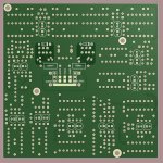
Ok, PCBs arrived.
Errata:
- LM317/337 are swapped. Their 2 and 3 pins should be switched prior to mounting. What a silly mistake
- PSU input is buried in PS caps - pretty hard to get there after you put all the components.
- Not enough space for regulator heatsinks (i knew it). Could be fixed by squeezing the regulators inwards (there is enough space for this).
- Mounting holes require tiny screws (standart M3 screw but with small (conical) head).
Some pictures...
s3t.it> Active crossover: AXO3
Directly:
http://s3t.it/data/uploads/axo3assembledshowoff.jpg
http://s3t.it/data/uploads/axo3assembledcloseup.jpg
http://s3t.it/data/uploads/axo3assembledbottom.jpg
http://s3t.it/data/uploads/axo3pcbstack.jpg
http://s3t.it/data/uploads/axo3pcbtop.jpg
http://s3t.it/data/uploads/axo3pcbbottom.jpg
http://s3t.it/data/uploads/axo3pcbcloseup.jpg
Little bit of updates to software:
Control points are draggable, and the graph is recalculated in real time while you drag the point. You get smooth frequency response manipulation.
Q for notches is changed by right-click-dragging of notch control point.
- Added phase plot to frequency response graph - looks better now. It's color is yet to be changed to something less aggressive than red.
Screen:
Demo:
http://s3t.it/data/uploads/plotterdemo5.zip
In the future i'll add biquad parameters generator, so you could use this program for DSPs too.
Adding enclosure/port simulator would be nice, as well as baffle (edge-like).
Frequency response import is a must.
Last edited:
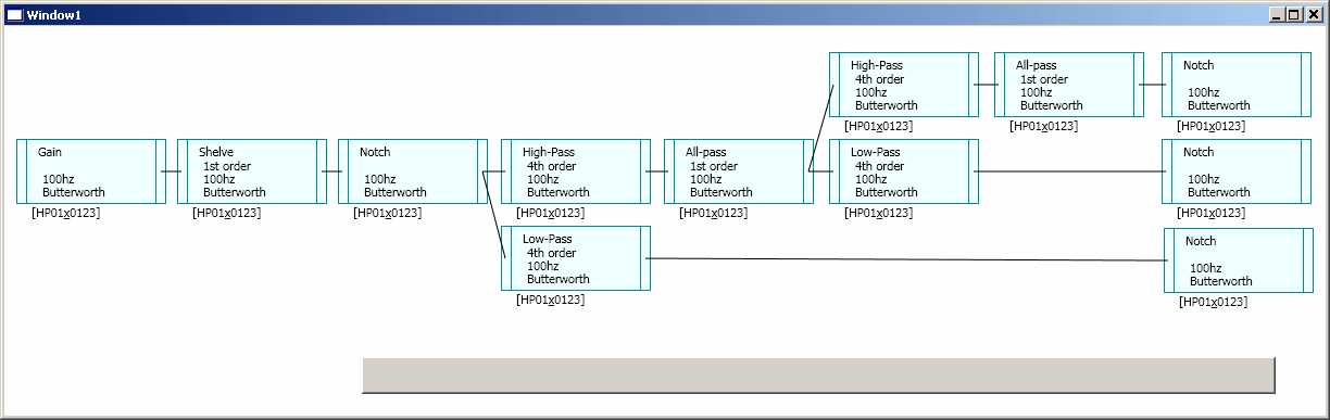
I have resurrected the filter designer project, with some updates from last week:
- Now i am able to plot frequency/phase responses of digital biquads
- I have made a GUI for chaining filter blocks into signal paths:
Implemented FFT (FFTW3-based) with various window functions and smoothing (currently works with WAV files and built-in noise generators):
- White/pink noise generators.
- WAVe file read
For now:
- No sound input/output
- No biquads calculator from actual transfer functions - probably, i'll need to do the math myself/grab it from books/internet.
- No solid synched envirement
The idea:
1. Take analog transfer functions (filters)
2. Chain them in the blocks-designer
3. Modify their parameters with control points on the graph
4. Generate digital biquad coefficients for the actual transfer functions
5. Apply the biquads/signal path to some DSP software core (in the program, or external plugin for foobar)
6. Play white noise/impulse/whatsoever thru these digital filters, and measure response of resulting speaker+filter combination with microphone
7. Display the measured response on the graph, where you have control points from step 3.
8. Repeat it.
The idea behind this is to keep everything "realtime", i.e. when you move the control point, it changes biquad coefficients, and the playing music passes thru these coefficients - and you hear what you are doing in real time (as well as measure it with built-in functions generator/FFT).
When you settle on particular filter configuration, you "build" it for following targets:
- Analog board from this thread (or any other)
- TAS3108 DSP board (to be designed)
- Software Foobar 2000 plugin (to be designed) (maybe winamp too)
- Other platforms - as biquads list (or any other way, need to reverse-engineer the particular applications).
All this i'd like to put in Microsoft Visual Studio-styled environment (MDI).
Kinda WYSIWYG editor for filters
Wavelets, CSD et cetera would be nice, but the features listed abowe should be implemented first.
Todo:
- Frequency response import.
- "Box" control point, for modelling speaker boxes
- "Real Bafflestep" control point for baffle diffraction simulation (where could i find the math equations/theory for this?)
Last edited:
- Status
- This old topic is closed. If you want to reopen this topic, contact a moderator using the "Report Post" button.
- Home
- Source & Line
- Analog Line Level
- XO3: The 1/2/3-way Active Crossover/filter PCB. Design suggestions welcome!