You're wrong in several aspects. Firstly i2s is a stereo format. Always. No multi channel support, no mono support. That's want lrck is for, deciding what is left and right channel data.
Secondly i2s is always 32bit words wide. Msb first. So consumers like dacs begin to read the 32bits for one channel starting at the msb, read 16, 24, 32 bits - how many they need and ignore 16, 8, 0 bits of the 32bit word if they don't need them. So a 16 bit DAC will not be confused by 32 bit data, it will simply ignore the 16 bits lsb of data.
Secondly i2s is always 32bit words wide. Msb first. So consumers like dacs begin to read the 32bits for one channel starting at the msb, read 16, 24, 32 bits - how many they need and ignore 16, 8, 0 bits of the 32bit word if they don't need them. So a 16 bit DAC will not be confused by 32 bit data, it will simply ignore the 16 bits lsb of data.
Are you talking about I2S hardware bus, or I2S PCM data format (Philips)?Secondly i2s is always 32bit words wide.
For I2S data format, IIUC it doesn't have to be 32-bits wide (although many USB boards default to that). The frequency of BCLK can be set to for 16, 24, or 32-bits can't it? Many USB boards can be configured that way, and so can many DAC ICs.
If the topic is what is commonly referred to as I2S hardware bus, it can be used for various formats not all of which are necessarily 32-bit wide. It can support PCM, Native DSD, and multi-channel TDM (with the latter two being generally being 32-bits wide, again IIUC).
https://en.wikipedia.org/wiki/I²S
https://www.infineon.com/dgdl/Infineon-Component_I2S_V2.0-Software Module Datasheets-v02_07-EN.pdf?fileId=8ac78c8c7d0d8da4017d0ea2ed3c2596
Last edited:
Ah, I definitely made one mistake: The "2" in "I2S" definitely means stereo. The systems I've designed that support 32 channels are called I32S, and the systems supporting 8 channels are I8S.
That correction in mind, I agree with Mark that I2S does not have to be 32 bits wide. Mackie (LOUD Corp) consulted with Tektronix to add a module to their digital 'scope for digital audio, and you could specify the number of data lines, the number of channels per line, and the number of bits per channel. There does seem to be a limit of 8 channels per data line, but higher channel counts simply use more data lines.
I can guarantee you that the XMOS solution we were working on did not use 32 bits per channel. It had 32 channels, and there simply isn't enough bandwidth to waste an additional 33% on extra bits to jump from 24-bit to 32-bit.
OK, just looked at the I2S specification again and it does not tak about a fixed word length. So I have been wrong there talking about a fixed word length of 32 bits. In practice I never have seen anything other than 32 bits. Probably because 16 bits is too small for most folks nowadays and 24bits would require weird clocks with multiples of 1.5 times the clock frequency like for example 18.432 MHz instead of 24.576 MHz (for the 48 kHz family).
A quick mouser search later I have to stand corrected. Actually that frequency is not so weird after all, 621 different oscillators with this frequency are listed, only 34 of them in stock though. Might indicate that this was more common at a certain point in time and now it isn't anymore?
Do you have an example I2S output board that does this for 24bits?
Anyways. If the DAC chip has an I2S compliant receiver it still must be able to handle any word length thrown at it and discard bits that it does not need or zero stuff missing bits, all according to the specification.
"I2S hardware bus" is a misnomer at least if referring to anything else than I2S.
I2S bus has 3 lines (or wires):
-bit clock
-word clock
-data
DSD and TDM have different content on 3 wires so these should not be mixed with I2S bus. More proper term for all these would be 3-wire bus.
I2S frame length is typically 64 bits so it can fit two 32-bit words. If word length is 16 or 24 bits the remaining bits are not used (normally driven low). However some I2S devices use 32 bit or 48 bit frames.
Btw the 2 in I2S should more look like I²S, translating to IIS, inter IC sound. Does not have anything to do with stereo ")
And one more thing, I2S is not limited to any number of data lines. Each data line can be seen as part of a separate I2S bus and there can be an arbitrary number of them. Actually I modified the firmware of my XMOS board to be able to handle up to 14 (7 stereo) channels of192k/24bits. No problemo.
And one more thing, I2S is not limited to any number of data lines. Each data line can be seen as part of a separate I2S bus and there can be an arbitrary number of them. Actually I modified the firmware of my XMOS board to be able to handle up to 14 (7 stereo) channels of192k/24bits. No problemo.
IME an I2S/PCM interface is a block with a common clocking circuitry and one or several data input/output lines. Each data IN/OUT line has a FIFO with IRQ/DMA transfer, but the clocking is common. Typically the burst 32-bit samples transfered via DMA are distributed to the active FIFOs on round-robin basis. I have seen a SoC with individual DMA transfers for each data line (do not remember the model anymore).
Some I2S interfaces can be configured to split the incoming 32bit words from RAM to 16bit halves for two 16bit channels.
Either multiple I/O lines are used (then each line carries only 2 channels), or the first line can be switched to the TDM mode and carries all X channels in the TDM mode.
Slot (i.e. one channel) can be configured from 8 to 32 bits, the default is often 16 or 32 bits.
Format can be configured I2S, left-justified, right-justified, sometimes first-bit shift can be configured, clocks inversed etc.
On some ARM SoCs each direction has it's own lrclk/bclk line and the IN and OUT direction can be clocked asynchronously when in the slave mode (but IN/OUT running at the same samplerate, with many common configs) as the DMA IN and OUT are independent. That can be quite handy in some situations.
This is my experience with full-blown ARM SoCs (unlike the Broadcom hack in RPi), I have no experience with STM32 etc.
As of the codec chips - the TDA154X chips pre-date 32bit-slot I2S. Some older codecs accept only 16bit or 24bit slots, no 32bits.
Some I2S interfaces do not offer 32bit slots, only <=24 bits (like the legacy PCI ICE1712/24 10ch I2S controllers which can output 16/18/20/24 I2S slots but accept only 32bit samples on the DMA (i.e. the OS driver) side).
Last edited:
Yeah, it doesn't work even if you use MacOS to play a 16-bit file (the output is still 24-bit, which the DAC doesnt seem to accept). Can't really add more to the chain, so will have to look for other solutions.Normally a 16 bit DAC should just care for the 16MSB and ignore the rest as it cannot meaningfully interpret it anyways. Maybe such old chips as the TDA1543 is having trouble with non zero input after the 16MSB? you could try with camilladsp inbetween and set the ouput bit depth to 16bit.
I do not know XMOS options, but standard solution for USB receiver -> 16bit DAC would be configuring the USB receiver to report 16bit format only in its USB descriptor and configuring the output I2S format to 16bit slot. That way the USB audio driver in the computer would not accept any other format but S16 and the OS/app would have to scale the sample bitwidth. I would be surprised if MacOS UAC support did not do that automatically, even if internally its CoreAudio layer uses float32 (IIRC).
macOS CoreAudio has a USB Audio Class compliant driver that will correctly handle a device that reports 16-bit only support, as well as a device that offers multiple bit depths including 16-bit.I do not know XMOS options, but standard solution for USB receiver -> 16bit DAC would be configuring the USB receiver to report 16bit format only in its USB descriptor and configuring the output I2S format to 16bit slot. That way the USB audio driver in the computer would not accept any other format but S16 and the OS/app would have to scale the sample bitwidth. I would be surprised if MacOS UAC support did not do that automatically, even if internally its CoreAudio layer uses float32 (IIRC).
As for the XMOS device, I haven't looked at the firmware source, but it should be relatively simple to run the USB at a different bit depth than the I2S bus. The data buffer would certainly need to adapt to the different bit depths on input and output, but that's also rather straightforward (unless you want the XMOS device to dither from 24-bit to 16-bit).
Limiting USB to 16-bit will not automatically reconfigure the XMOS peripheral for I2S traffic with 16-bit data - you may have to do this manually in the source code. XMOS has very flexible clocking and data formatting options, so look at the settings on the I2S side of the firmware.
I was wrong eariler so take my information with a grain of salt here.
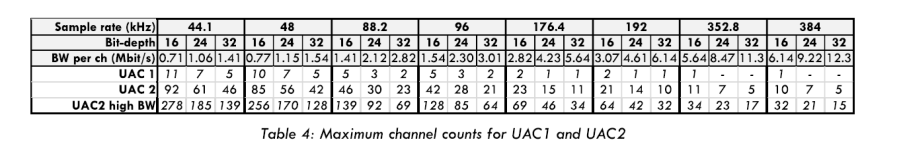
I modified the XMOS firmware to accept 16/24 bit only over USB instead of 16/24/32 bits. I2S output was left at 32 bit frames/words though. this modification was relatively easy beause zero stuffing was already implemeted in there for the 16/24 bit cases. Why I did that was to save bandwidth on the USB link as there is a limited bandwidth available. UAC2 does a 1024 byte frame every 0.125us which amounts to 65.536Mbits/s.This can barely fit 14 channels of 24bit PCM audio @192kHz FS/24bits.
Sadly I will not be able to share the firmware code, or at least at the time of modifying it (more than three years ago), I was told so. XMOS terms of licence prohibit this. Please correct me if I'm wrong on that...
Modifying it to output 24 bit words over I2S would most likely require a major rework, not only in software but also in hardware as the used 22.5792/24.576MHz oscillators would have to be changed to ones operating at 75% of their respective frequency. Modifying it to 16 bit words over I2S might be done entirely in firmware. How easy it is - I can not comment on it as I'm not an experienced XMOS developer. The language is non-standard and I managed to get things working based off of the 8 channel USB example code (which diyinhk obviously used as their starting point as well) and just poked around, fiddled and got it to work. Being a software developer in my day job helped (standard procedures of poking, trying, troubleshooting, interpreting unknown code) but not to a very big degree. xc is just a different beast of language for a very different beast of hardware platform, not comparable to any von Neumann CPU architectures lilke x86,amd64,armv? etc...
. UAC2 does a 1024 byte frame every 0.125us which amounts to 65.536Mbits/s.This can barely fit 14 channels of 24bit PCM audio @192kHz FS/24bits.
Also did this a years ago, I used just 8 channels PCM-192/24 and 6 at DSD128 in one design, and 16ch PCM96 in another.
P.S. Are anybody implements UAC2 high BW?
Ross (from XMOS) promised to do this few years ago....
This can give us much higher number of channels (or higher sample rate).
Alex.
Attachments
@ Raj1: on WaveIO, the output I2S format is fixed on 32 bits/word. 24 can be used and rest padded with zero. On 16 bit DACs I got reports on issues like yours so what I really have to do is to switch that on 16 bits format for this particular case.
BUT, as most of us noticed, XMOS firmware and XC language aren't not easy to cope with. I saw that in the past time frame they ditched XC language as well.
As for me, now I'm more focused on hardware side of things rather that software but I'll have to address this I2S issue in future WaveIO iterations as well!
.. most likely made on my therms (PLDs) rather than XMOS firmware...
IMO the 16bit truncation is best to be done at the OS level which may be expected to provide proper dithering. Also sparing USB bandwidth is a good technical practice (though not critical for TDA154X )
The high bandwidth/multiple transactions should be supported by Linux/Win/MacOS audio drivers (and likely Android as those are linux drivers). RME devs claim it's not supported by iOS which made them avoid this mode in their multichannel device https://forum.rme-audio.de/viewtopic.php?pid=178246#p178246 .
)The high bandwidth/multiple transactions should be supported by Linux/Win/MacOS audio drivers (and likely Android as those are linux drivers). RME devs claim it's not supported by iOS which made them avoid this mode in their multichannel device https://forum.rme-audio.de/viewtopic.php?pid=178246#p178246 .
Found almost same already here: https://www.diyinhk.com/shop/audio-...d256-high-quality-usb-to-i2sdsdspdif-pcb.html
(you can delete this or keep for others)
(you can delete this or keep for others)
- Home
- Source & Line
- Digital Line Level
- XMOS-based Asynchronous USB to I2S interface