That would depend on what you mean by noise (many people use noise and interference interchangeably - which can cause confusion). If you mean interference, then electric field interference is stopped by adding a short. Magnetic field interference is facilitated by adding a short, as that creates a small loop.
Noise results would depend on whether you have voltage noise or current noise dominating at the input.
As always in electronics (and almost everything else), you can't rely on a recipe; you have to gain understanding. All your threads seem to follow the same path: give me a simple recipe to solve this problem. In most cases there isn't a recipe; in some cases there isn't a real problem!
Thanks again. If i understand well you mean that when they carry out noise measurements they perform the test in both ways, with the inputs shorted and open, to see the sensitivity of the unit to both electric and magnetic field interference ?
In the meantime i have bought a pair of XLR cables so that i could cut them open and connect the wires with a resistor or leave them open.
In this way i could evaluate both electric and magnetic field interference.
Thanks a lot again, gino
the third wire of the 3core mains cable is "Protective Earth", PE. Don't call it ground. That would just add to the confusion.Yes i can confirm on my side.
But still i have problem to understand if the metallic chassis of an equipment must be connected to the central pin of a mains plug that i think is ground.
I remember i did this and i got a loud noise on an amp.
And actually the center pin was left open.
regards, gino
Here in the UK most will just refer to it as "earth" and most would understand what that means.
Do not disconnect the PE to Chassis connection. Make it permanent. That is the regulation.
No. You are confusing noise and interference. People may do noise measurements with open and short on input, to separate current noise from voltage noise. You should not worry about such things; learn the basics first.ginetto61 said:If i understand well you mean that when they carry out noise measurements they perform the test in both ways, with the inputs shorted and open, to see the sensitivity of the unit to both electric and magnetic field interference ?
Please please stop looking for simple recipes. Instead, build and measure what you can within your understanding. Don't try to run before you can stand up without falling over.
the third wire of the 3core mains cable is "Protective Earth", PE. Don't call it ground. That would just add to the confusion. Here in the UK most will just refer to it as "earth" and most would understand what that means.
Do not disconnect the PE to Chassis connection. Make it permanent.
That is the regulation
Hi and thanks again.
Then i understand now that i have used a very dangerous amp because i remember perfectly that the central pin was not connected to the unit chassis.
And when i try i got an ugly and loud sound from the speakers.
I am not using that amp anymore.
I found the symbol for class 2 components.
An externally hosted image should be here but it was not working when we last tested it.
If there is no this symbol on the back i will check for the connection chassis to protective earth for sure.
Thanks a lot again, gino
No. You are confusing noise and interference.
People may do noise measurements with open and short on input, to separate current noise from voltage noise.
You should not worry about such things; learn the basics first.
Please please stop looking for simple recipes. Instead, build and measure what you can within your understanding. Don't try to run before you can stand up without falling over.
Well then i can only measure V and R because with L and C i have already problems.
As i said i have discovered this Arta software because a guy uploaded some noise measurements on a usb interface that i also have.
This interface has some noise issues because there are cables inside that pick up noise generated by the smps. The cables act as antennas.
So the idea was to try to reroute these cables to minimize the noise.
I have already bought some adeshive clips to try to keep the cables far from the smps. Now they are flying over it.
This was the project and this the link to the thread.
http://www.diyaudio.com/forums/power-supplies/291288-smps-_-shielding-options.html
If i can reduce the noise just a little i am done.
I have been advised to cover the cables with copper tape but then they become conductive on the outside.
The guy above mentioned has replaced the original power supply with a new linear one ... result zero noise. Perfect unit.
I would like to keep the original one that has quite low ripple but bad shielding.
Thanks a lot again, gino
If you want a realistic noise measurement for a mic pre use one of those xlr cables and put a 600ohm resistor across the +/- of the far end. 600ohms USED to be the standard mic output impedance. Or check your mics, and see what they say for output impedance and try those resistors.
Most likely the internal circuitry was incorrectly wired.Hi and thanks again.
Then i understand now that i have used a very dangerous amp because i remember perfectly that the central pin was not connected to the unit chassis.
And when i try i got an ugly and loud sound from the speakers.
I am not using that amp anymore.
............................................................
Thanks a lot again, gino
It took over a decade to get the pro audio equipment manufactures, to correctly wire XLR pin1.
Now at two decades, some audiophile equipment manufactures are still doing it incorrectly.
If you want a realistic noise measurement for a mic pre use one of those xlr cables and put a 600ohm resistor across the +/- of the far end.
600ohms USED to be the standard mic output impedance.
Or check your mics, and see what they say for output impedance and try those resistors
Hi thanks a lot for the very valuable advice.
Yes that is what i need for the mic inputs. My trivial thinking is that the lower both noise and distortion the better the sound.
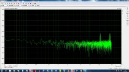
I am attaching the graph of noise but with inputs open waiting for the cables and resistances.
Unfortunately this interface i am testing has some noise issues.
I have read that they vanish extracting the smps from the unit.
The dream is to be able one day to trim the peaks ..
Thanks again, gino
Attachments
Most likely the internal circuitry was incorrectly wired.
It took over a decade to get the pro audio equipment manufactures, to correctly wire XLR pin1.
Now at two decades, some audiophile equipment manufactures are still doing it incorrectly
Hi and thanks a lot for the very valuable advice.
That amp was a semi-industrial unit ... almost handmade.
Good sound but some building issues. The sound was interesting.
From now on i will check for the class 2 sign and in the case of absence i will check if the chassis is earthed. For sure.
Thanks again, gino
Are you seriously worried about noise or interference at -120dB????
Hi ! disappointed is the right terms

With a plastic spoon i tried to move the cables inside running close to the smps but the noise stays unchanged.
The base line is lower ... however. This means that there is some potential.
The next step is try some distortion measurements.
Regards, gino
- Status
- This old topic is closed. If you want to reopen this topic, contact a moderator using the "Report Post" button.
- Home
- General Interest
- Everything Else
- XLR Shorting Plugs