I may have missed something, but if the whole point of this exercise is to be able to reverse the phase of one channel, why not reverse the speaker wires for that channel and move on?
That assumes you already can make a working connection between units other than through the XLR connectors.
If the point is that you cannot now connect the pre and power amps together, then I will shut up and watch.
That assumes you already can make a working connection between units other than through the XLR connectors.
If the point is that you cannot now connect the pre and power amps together, then I will shut up and watch.
Thanks for the help,
Pink mouse and netlist you both seem to be getting ideas forward I can understand.
I can quite happily cut holes in the back of my case (lets face it all you need is a bit of dynamite and some luck...or a drill.)
I am a semi compotent solderer though am prone to mistakes. (read below if you want to hear what the worst one was WARNING its pretty grim)
unfortunatly these are the things i cannot understand
"Use the DRV134. You will need the two chips, about ten caps, and about two square inches of perf board. You will also need to open up your pre, find the voltage rails for the preamp"
netlist I am stuck on the parts 2-4.
I have had NO electronics training EVER, i just know a bit of the thoery behind from taking chimistry at uni (which loosely relates to physics which is relevant).
Will both these circuits improve the quality?
If not is it possible to buy better quality components?
ok now for the painful story.
Sitting at my table soldering some wires with a HEAVY pair of bullnose pliers half off the table. Accidentally solder my finger (as you do). Elbow kicks back and hit pliers Hard. The pliers then sail into the air just missing my face (just to give you an idea how high they went before returning to the ground/my groin.
Well you can guess where they landed...to cut a long description short. I was wearing Jeans and the pliers still managed to draw blood! it hurt.
Ouch!
Ok, can you open up your pre and take a couple of photos. That way, we can probably guide you in tracking down the power rails. I will sketch up a quick circuit diagram for the components in the next hour or so and post it here. It really isn't as difficult as we made it sound, Hugo and I were just discussing best implementation.
Oh, for the holes, I find shaped charges make the neatest cut!")
Ok, can you open up your pre and take a couple of photos. That way, we can probably guide you in tracking down the power rails. I will sketch up a quick circuit diagram for the components in the next hour or so and post it here. It really isn't as difficult as we made it sound, Hugo and I were just discussing best implementation.
Oh, for the holes, I find shaped charges make the neatest cut!
Pink mouse I was having a look at your circuit. I know I have only seen the top half but it does not really look that complicated!
I also connect the three surround channels of my PC directly to my second power amp (RB-993 also XLRd).
I have no volume control on the surround channels as i have no pre for them.
Am i right in guessing that your pretty circuit is essentialy a volume control with XLR outputs that takes unbalanced inputs?
I am quite good at following instructions (if the instructions are good) would you be able to tell me how to do it? (please, its worth a hugh and the knowledge that you managed to teach an ignoramous advanced electrical theory)
Hmmm shaped charges!
I think I am going to do dinosaur shapes.
I suddenly realised how hard opening up my case is going to be...I forgot i epoxied it to the bottom of one of my hifi shelves.
I had run out of room on my rack and couldn't be arsed to make a bigger one
I will get some photos somehow...I could unsrewthe top plate leaving that on my rack.
ooh have to goto work, see you later and thanks
Peter
Peter Scowcroft said:...I forgot i epoxied it to the bottom of one of my hifi shelves.
ROTFLOL!
Ok, I will post the driver part later today, and the Mk2 buffered version when finished and I have checked it all out.
Hi Mousey,
Any more progression on how to make my new toys?
I promise i won't greatly injure myself following them...much!
It is not like I am using anything dangerous...like soldering iron, pliers! , mains voltage electricity oh and not to mention a dinosaur shaped platic explosive!
Any more progression on how to make my new toys?
I promise i won't greatly injure myself following them...much!
It is not like I am using anything dangerous...like soldering iron, pliers!
, mains voltage electricity oh and not to mention a dinosaur shaped platic explosive! 
I can borderline understand this. I'm at the border though on the wrong side =-(
I have a few questions!
1) Where do i connect the inputs signal and return. Which areas do i glue to the three XLRs, signal, inverse signal, return?
2)Where it says earth what do i stick that too?
3) there are some capasitors (i'm guessing because of the uF) one has a circle and a positive which i am assuming is a normal cap...what is the other one?
What do I ask for in the shop EXACTLY and what shop?
4) what is the chip called and where can i buy it?
5) you mentioned that this had to be connected to a power supply! Where do i connect it and what voltage?
6) as i probably will do a low grade test unit (depending on component cost) would it be possible to run that off a battery so i can fit it externally?
7) I have NO idea what this will cost, are there any components I can get of a better quality that will improve the sound?
8) Do you have a fave kind of beer because i will probably have to mail you a 6 pack to say thanks for the help!
9) Thankyou for the help so far.
p.s. It might be easier if you e-mail me at peterDOTscowcroftATtiscaliDOTcoDOTuk
thanks again
That's ok Peter, no problem. I think this is also informative enough to keep it in the public domain, after all, I'm sure there are others out there with the same problem!
Anyway, answers...
1) For this you need to do a little research. On the back of your power amp it will give a polarity for the XLR connector. It will be either pin 2+, pin 3-, or the other way round. The + and - outs connect to the appropriate pin in the XLR connector. The third pin is for earth, we'll come back to that later.
2) Later...
3) The capacitors with the circle around them are electrolytic, and have a positive and negative pin. They must be mounted the correct way or they will go bang! the third item down on this page is the kind of thing you're after. The other components are also capacitors, and the seventh item on this page will do the trick.
4) The chip is a Burr-Brown DRV134. I got them from RS components, but if you can't get them, I may have a couple spare.
5) The ideal supply would be run from your existing pre, +15v,-15v. We would have to track down the rails in your amp.
6) Yes, two 9v batteries would work fine for a temporary solution.
7) Not that much, probably about a tenner.
8) Ooh, now there's a question. I will have to think about that one...
9) No problem, anything for a fellow Yorkshireman.
p.s. You will notice that I haven't got back to earthing. That will be a whole installment in itself..
For the Xlr it is a 3 pin connector. 33 kohm and 1 volt.
I can't see anything else apart from that =(
I am having a look round at maplins at the mo for gear.
oh for the love of god it is confusing!
What is the board you have glued your circuit called?
What wiring do you reccomend or should i use that conductive paint listed on maplins?
Remember i have NO electronics experience or training.
Are you a Black Sheep or Timmy Taylors man?
Ok, well we will go with the UK standard for XLR, pin 2 hot, (if anyone knows this amp better, please chip in!). This means that the +output from the chip goes to pin 2, and the -output goes to pin 3. Pin one is earth. I am deliberately leaving earth connections 'till last, to avoid confusing you more than required.
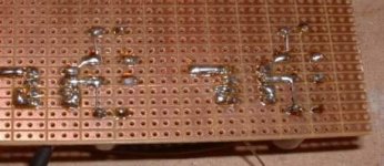
The board I use for construction is called Tripad board, and you can get about twice as much as you need for both boards for about a fiver from Maplins.
For wiring, for the most part we will use the pads on the board, and small interconnects cut off from the components once they are mounted. For the signal wiring, we need screened twisted pair. Don't bother buying this, send me your address and I will send you a couple of metres, I have a drum with the best part of 150m on, so I can easily spare you a little!
And now, a short intermission, while I eat my tea...
Ok to clarify i need for each channel:
GenElect 100uF 16V low profile electrolytic capacitors x 2
Polyester 0.1uF film capasitor x 2
Some tripad board
and of course some wire.
I have some Naim interconnect wire I am not using would that work? (4 core + shield)
I cannot find anywhere that sells the DRV134! any hints or do you have some spares i could purchace?
This sounds so exciting!
Did you have a good tea? cheezy beans on cheese and toast for me.
Don't worry my interconnects wern't that pricey....apart from the £130 per metre ones....which is all of them!!
I liked the cable because it DID make the sound different!?
I am just going to chop the RCAs off and o a bit of resoldering.
Cant wait to try this.
Eventually I am going to stick something like this on the back of my CD player and run everything balanced the whole way through!
I liked the cable because it DID make the sound different!?
I am just going to chop the RCAs off and o a bit of resoldering.
Cant wait to try this.
Eventually I am going to stick something like this on the back of my CD player and run everything balanced the whole way through!
- Status
- This old topic is closed. If you want to reopen this topic, contact a moderator using the "Report Post" button.
- Home
- General Interest
- Everything Else
- XLR modification