Some more progress yesterday
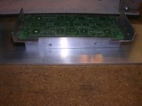
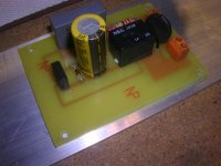
Both filter boards are now ready for wiring up and installation.
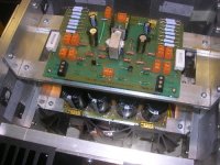
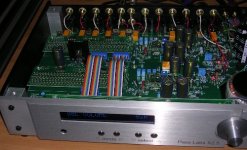
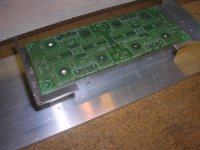
Here the intended view of the PS and main Pcbs.
My plan is to match the power fets over the weekend and insall them and be able to test within a fortnight.
Ian
Both filter boards are now ready for wiring up and installation.
Here the intended view of the PS and main Pcbs.
My plan is to match the power fets over the weekend and insall them and be able to test within a fortnight.
Ian
Attachments
Ian, great job so far! The pics shows that you are very meticulous and pay attention to the details") Taping up fets is a new one Aluwork takes time, thats obvious for us that actually build amp's now and then, but yours must have taken a lot of time? Considering the attention you give to details, I am rushing my amps
Taping up fets is a new one Aluwork takes time, thats obvious for us that actually build amp's now and then, but yours must have taken a lot of time? Considering the attention you give to details, I am rushing my amps
Steen
Taping up fets is a new one Aluwork takes time, thats obvious for us that actually build amp's now and then, but yours must have taken a lot of time? Considering the attention you give to details, I am rushing my amps Steen
Zen Mod said:I like that Alu chunk in middle
It goes hand in hand with the way the amp images.
steenoe said:Ian, great job so far! The pics shows that you are very meticulous and pay attention to the details
Steen
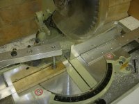
Yes, I started around November last year. I have been building aluminium boxes since 2001 now and have gradually build up some experience and techniques. Having a good workshop helps and recently bought a Makita Mitre saw and aluminium blade.
I could not imagine not tapping the power fets these days, its makes assembly so much easlier, I just use an allen key to carefully tighten the M3 hex bolts.
That saw is marvelous, so accurate and saves me hours. But still there is only so much you can do in an afternoon over the course of each weekend.
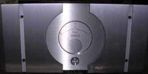
Looking at the X250.5 and the X2.5 is my inspiration though.
Pass Labs are true masters of their chassis.
Attachments
More chunks of aluminium...
The diodes would not seat property on the little pcb heatsinks so I had to look for another solution.
Given the surface area of the lower outer panels I used a 20x 25mm solid bar between the diodes which will be thermally bonded to the 80 x 260mm panel.
The bar was tapped with M3 holes for the rectifier pcb and M4 to attach to the panel.
Attachments
macka said:Thanks,
I just hope it works!
Well, if it goes BANG, at leats it looks good
Magura

jacco vermeulen said:I can't read P-A's date of birth and social security number on that board.
Must be on the other side
Apparently
What kind of blade is that on the saw, Ian ?
An aluminium one!
Its a cardbide blade by a local company cost about AUD$180.
I use a lubricant
Ian
This project has been a long time in the wind but it has been an interesting journey.
If you have been following Graeme's thread here you can see I looked at Jfets on the input stage. After some experimentation I settled from Graeme's recomendation of 26 db gain.
They are a very different beast to the venerable IRF9610
http://www.diyaudio.com/forums/showthread.php?s=&postid=1505601#post1505601
Tonight I switched back to the 9610 input stage.
They are certainy different. The 2SJ74 being more delicate, refined and cleaner in the top end while the 9610 has a darker tonality and perhap more drive in the bass.
Bearing in mind I am using relatively low supply rails of +-24 volts it ocurred to me that perhaps there is simpler means to an end .
To be continued
Following some assistance from Nelson on setting the gain options with the Jfet X Aleph he also hinted at using some small Mosfets like those used in the Passdiy opamp article.
The Zetex on line product selector shows the range here.
I settled on the ZVP2110A, its E line T092 compatible and is rated at 700mw, 100VDS device .
http://www.zetex.com/3.0/pdf/ZVP2110A.pdf
Not knowing what to expect I matched a pair last night for the standard bias of the X Aleph input pair and popped them in directly (not cascoded). I have not attempted to optimise anything yet. Dissipation is in the order of 200mw per device..they are comfortably warm to touch.
It was very interesting.
These tiny little mosfets sound quite nice straight out of the packet.
My subjective evaluations can only be taken with a grain of salt but I applaud Nelson for pointing out that tis the active gain device that really effects the sound of an amplifier. I think we should build a temple out of Aleph's for him one day.....
Direct comparison to the IRF9610 under the same conditions suggests the ZVP 2110A is cleaner and less dark. The midrange being more tuneful and open sounding, the highs a bit more airy, the lows less thick but firm.
The recording I used is Miles Davis "Kind of Blue".
http://en.wikipedia.org/wiki/Kind_of_Blue
Today I had another look at these tiny mosfets.
Following some more subjective evaluations and other comparisons I determined intuitively rather than scientifically that there was either more open loop gain than I need or too much feedback.
Not wanting to mess with bias of these mosferts quite yet I decided to relax the feedback by reducing R19/R29 by half their value to 11K. R16/R30 remaining at 220K.
Manipulating this resister also has the effect of a voltage divider on the input signal so in overall terms I figured the gain was about the same.
The moment of throwing the switch came.
These tiny mostfets are beginning to talk to me Kent... (in joke)
The sound now is more alive, the bass extended (not over damped as before) and there is a sense of ease and timing in the presentation that I would descibe as toe tapping
iMac
- Status
- This old topic is closed. If you want to reopen this topic, contact a moderator using the "Report Post" button.
- Home
- Amplifiers
- Pass Labs
- X Aleph Project Down Under