Peter,
Seems I did not think my F4 project through, since everything I have is balanced these days I need another pair of boards. Do you have any more? How fussy are these on voltage I have a pair of 20v transformers and what would be the recommended VA for a pair of boards?
thanks
Bill
Seems I did not think my F4 project through, since everything I have is balanced these days I need another pair of boards. Do you have any more? How fussy are these on voltage I have a pair of 20v transformers and what would be the recommended VA for a pair of boards?
thanks
Bill
That how it looked to me, but when you first proposed them I thought you mentioned having the connections connected with a trace and if you wanted to use the caps then scratch off the trace. I realize that you changed your mind , but the wording was still a bit confusing to me!
I hope this helps future confused generations and eliminates Burning Amps!")
I hope this helps future confused generations and eliminates Burning Amps!
ipolyakov said:I just realized that if we don't use C5 and C6 capacitors, we cannot solder to two ground holes near them. They would be not connected to anything. Correct?
Not really, even if you install the caps, you still need to provide the ground connection: those two ground holes are optional too.
If you look at F4 amp schematic, you will notice that power ground is not there, only the input signal ground.
The power ground is located on PS board, and this is where speaker ground connects. Signal ground reference is taken from PS board, with a separate wire, and connects to GND point on amp board which is beside SG point (SG is used for ground connection from input RCA).
The GND on the opposite side of the board is only for C5/C6 and if those caps are being used you need another ground wire from PS board.
Variac said:That how it looked to me, but when you first proposed them I thought you mentioned having the connections connected with a trace and if you wanted to use the caps then scratch off the trace. I realize that you changed your mind , but the wording was still a bit confusing to me!
I hope this helps future confused generations and eliminates Burning Amps!
The traces to be cut are on PS board. The locations are marked with white lines in a bottom layer. You cut them only if you are using Jensen 4 pole caps, this way the potential 4 pole design offers can be fully utilized.
Attachments
Peter Daniel said:
Not really, even if you install the caps, you still need to provide the ground connection: those two ground holes are optional too.
If you look at F4 amp schematic, you will notice that power ground is not there, only the input signal ground.
The power ground is located on PS board, and this is where speaker ground connects. Signal ground reference is taken from PS board, with a separate wire, and connects to GND point on amp board which is beside SG point (SG is used for ground connection from input RCA).
The GND on the opposite side of the board is only for C5/C6 and if those caps are being used you need another ground wire from PS board.
Peter,
Thanks. Now it's clear.
Igor
Peter Daniel said:Apparently those resistors are on backorder at DigiKey and Product Lead Time Estimate is for Oct 17.
The resistors are back in stock and I will order them tonight.
Attachments
Banned
Joined 2002
Re: PCB and semi kit
I think if peter put a resistor and capacitor kit together for the F4's Id buy 2 sets asap
WINK WINK NUGE NUGE!!
niner said:Peter, do you have any amp PCB and semi kit?
I think if peter put a resistor and capacitor kit together for the F4's Id buy 2 sets asap
WINK WINK NUGE NUGE!!
Resistor options?
Hi folks -
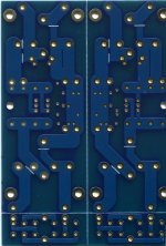
I've received my boards from Peter (beautiful, by the way), my transformer from Plitron, some heatsinks, and, just yesterday, a box from Digi-Key with caps, fuses, zeners, etc, so I'm real close to ready to go on this.
My problem is resistors for the main board. (I did get the 0.47 Panasonics that Peter made available.) I just priced Caddock MK132s, and they came in at approximately $165. I wouldn't mind a more economical approach, but I'm kind of stymied by minimum quantity requirements, like 5,000, for certain types of resistors (e.g., Phoenix) from some suppliers.
I do realize that we're still talking about building a great amp for pennies on the dollar, even with Caddocks, or, for that matter, Vishays, but has anyone sourced appropriate miniature resistors that don't cost an arm and a leg? Any suggestions would be appreciated. TIA - Pat
Hi folks -
I've received my boards from Peter (beautiful, by the way), my transformer from Plitron, some heatsinks, and, just yesterday, a box from Digi-Key with caps, fuses, zeners, etc, so I'm real close to ready to go on this.
My problem is resistors for the main board. (I did get the 0.47 Panasonics that Peter made available.) I just priced Caddock MK132s, and they came in at approximately $165. I wouldn't mind a more economical approach, but I'm kind of stymied by minimum quantity requirements, like 5,000, for certain types of resistors (e.g., Phoenix) from some suppliers.
I do realize that we're still talking about building a great amp for pennies on the dollar, even with Caddocks, or, for that matter, Vishays, but has anyone sourced appropriate miniature resistors that don't cost an arm and a leg? Any suggestions would be appreciated. TIA - Pat
While the resistors footprint is indeed miniature type, you are not limited in any way for those particular resistors. You can use any size, just install them vertically; with such a tight layout it will not make any difference.
Besides, Phoenix and Panasonic miniature resistors can be ordered from Digi Key in 5 pc. quantities.
Besides, Phoenix and Panasonic miniature resistors can be ordered from Digi Key in 5 pc. quantities.
My problem is resistors for the main board. (I did get the 0.47 Panasonics that Peter made available.) I just priced Caddock MK132s, and they came in at approximately $165. I wouldn't mind a more economical approach, but I'm kind of stymied by minimum quantity requirements, like 5,000, for certain types of resistors (e.g., Phoenix) from some suppliers.
Huh?
These are all from Digikey. Before you purge on Caddocks, order these first. There are only a few select spots in this circuit where better resistors might make a difference. For now, spend money on a quality power transformer, and a good 4 pole power supply like what Peter Daniel has designed.
See below. You guys owe me for this one!
(10) PPC1.00KZCT-ND RES 1.00K OHM METAL FILM .60W 1% 0 0.23800 $2.38
(5) PPC750ZCT-ND RES 750 OHM METAL FILM .60W 1% 0 0.23800 $1.19
(2) CMF47.5KHFCT-ND RES 47.5K OHM 1% 50PPM 1/2W 0 0.16000 $0.32
(10) PPC10.0KZCT-ND RES 10.0K OHM METAL FILM .60W 1% 0 0.23800 $2.38
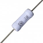
(20) P0.47W-3BK-ND RES .47 OHM 3W 5% METAL OXIDE 0 0.47600 $9.52
(5) PPC10.0ZCT-ND RES 10.0 OHM METAL FILM .60W 1% 0 0.23800 $1.19
(5) PPC27.4KZCT-ND RES 27.4K OHM METAL FILM .60W 1% 0 0.23800 $1.19
(12) CMF150HFCT-ND RES 150 OHM 1% 50PPM 1/2W 0 0.14900 $1.79
Best,
Anand.

Banned
Joined 2002
nycavsr2000 said:And here are the pots:
(2) 3296W-501LF-ND POT 500 OHM 3/8" SQ CERM SL MT 0 2.50000 $5.00
and
(2) 3296W-502LF-ND POT 5.0K OHM 3/8" SQ CERM SL MT 0 2.50000 $5.00
Have fun
Anand.
What is with the 500ohm pot ? that is not even on the F4 board, its 2 x 5k ones tho.
A few resistors in your list are for something else, like the 750 ohm one, and the 10ohm one.
- Status
- This old topic is closed. If you want to reopen this topic, contact a moderator using the "Report Post" button.