Samuel Jayaraj said:
I have got J176. Is this a suitable replacement for the 2SJ74/2SJ108 part in the F4?
Not quite the same...
This thread might help you:
http://www.diyaudio.com/forums/showthread.php?s=&threadid=99368
Peter:
Which of the F4 schematics is this board based on? The service manual, or this one posted later by Pass:
http://www.passlabs.com/np/F4R0.pdf
Which of the F4 schematics is this board based on? The service manual, or this one posted later by Pass:
http://www.passlabs.com/np/F4R0.pdf
luvdunhill said:Peter:
Which of the F4 schematics is this board based on? The service manual, or this one posted later by Pass:
http://www.passlabs.com/np/F4R0.pdf
The latest from NP
Banned
Joined 2002
Peter Daniel said:
The latest from NP
Thank's Peter,
Glad to see your helping out and keeping an eye out for us, good job.
Jase
This post explains it. If you read the thread it might have been tedious but you could have found out this info yourself.
http://www.diyaudio.com/forums/showthread.php?postid=1231125#post1231125
e-mail funds via paypal to the e-mail address peter lists there. When you send via paypal the is a text box where you can note what you are ordering.
variac
http://www.diyaudio.com/forums/showthread.php?postid=1231125#post1231125
e-mail funds via paypal to the e-mail address peter lists there. When you send via paypal the is a text box where you can note what you are ordering.
variac
Banned
Joined 2002
Variac said:This post explains it. If you read the thread it might have been tedious but you could have found out this info yourself.
http://www.diyaudio.com/forums/showthread.php?postid=1231125#post1231125
e-mail funds via paypal to the e-mail address peter lists there. When you send via paypal the is a text box where you can note what you are ordering.
variac
Attitude much ?
\Maybe it takes way to much time to look through so many posts. Ever thought about that ?
Peter,
I received some very beautiful boards last Monday. Many thanks!
Are you still planning to post more information regarding your power supply board? Now that I have the board in my hand, I’m thinking that it would also be great for small projects, such as the Pearl external power supply that I never built.
No pressure and no hurry either. I think I can figure this out from what you have already posted. But, I’m new at this and can use all the help I can get.
Thanks again,
Looney
Canadian post what more can I say, how about your management coming over here to show the Royal Mail management how it should be done.
I see nothing wrong with Royal Mail. They may be unprofitable but in my experience they are very quick+reliable.
Best
Giulio
Looneytunes said:Are you still planning to post more information regarding your power supply board? Now that I have the board in my hand, I’m thinking that it would also be great for small projects, such as the Pearl external power supply that I never built.
I'm glad you all like the boards, they came out pretty nice indeed, with thick traces and nice shine, and the color that is neither blue nor green
")
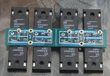
The PS board was supposed to be truly universal, I tested the diodes configurations this morning and it all works fine. Here a short outline:
The rectifier section is supposed to be separated and high power diodes mounted as in a picture below (they can be attached directly to a chassis for heat dissipation, isolation pads needed). The board is designed mainly for 3 pin rectifiers, but will work with other diodes packages as well. Here's MUR3060:
Attachments
- Status
- This old topic is closed. If you want to reopen this topic, contact a moderator using the "Report Post" button.