LOL, IN three years, NO ONE caught this?? Your Post #10.
2A3 Plate, 308 VDC 2A3 Cathode, 47 VDC Plate to Cathode difference is 251 VDC, ...NOT 361 VDC
The $$$ you spent on a new PT was due to your SIMPLE math error.
What you heard in improvement was the reduction of 480 Ohms divided by two, or 240 Ohms LESS OF SERIES RESISTANCES in the B+ filter to the Finals particularly, and to the rest of amp !!
From all your measurements, I will redesign this into a proper DC amp for Mr. Ed in this thread. Hes spent enough time listening to such a sub par design of a 2A3 amp, as this one truly is. You can add all the botique parts you want, but the design is DEFICIENT in many ways !! Starting with the supply.
Jeff Medwin 9-10-2016
Please read post #14 - what is the voltage across the 2A3, isn't that the same as your so-called "Golden Ratio"?
Post #10,
P-K was 308 Plate minus 47 VDC 0n the Kathode, or ...................261 VDC P-K.
K was at 47 VDC, using a 760 Ohms ( 10 Ohms for hum pot ) Rk. 47 VDC divided by 760 Ohms is 0.0626A.
DISSPATION of the 2A3 Plate is thus 261 VDC times 0.0626 A., .... equals 16.35 Watts.
If you change the power transformer, and achieve 250 VDC P-K, down from 261 VDC, and assuming a 47 VDC bias of the Kathode, you get 200 VDC times 0.0626 A. or .....15.65 Watts of Plate dissipation.
----------------
No, not the same as Golden ratio, but it IS one part of the iinformation needed to compute it.
Golden Ratio proportion is 62%.
Maximum rated plate dissipation on a standard 2A3 is 15 Watts, by the book. Most every manufacturer runs a 2A3 at close to maximum. That is 250 VDC P-K and 0.060 A. equals 15.0 Watts plate dissipation exactly.
This 15 Watt plate dissipation makes the usual 2A3 tubes SOUND thermally stressed, because it IS thermally stressed, running at 100%, the " max."
It is far better to drop current and keep voltage, ie 250 VDC P-K times 0.042 mA. equals 10.5 Watts of plate dissipation. 2A3 tube willl LAST longer and sound better, less stressed, at 10.5 Watts dissipation, assuming the rest of the amp is made properly, and optimally, which most manufacturers, DON't DO !!
Consider the Golden Ratio as this analogy : continuously running down the highway in your car, on the interstate, doing 62 MPH instead of 100 MPH. Your car can DO 100 MPH, but lower MPH has a LOT LOT easier, with less wear on the automobile.
BTW, I can NOT " FIX" the WPA 3.5 using the amp's existing Power Transformer. I was WRONG, mis-computed it. Yesterday I thought I could, but doing all sorts of PSUDing, I caught my error.
I can not apply a desireable FLYWHEEL or LSES B+ filter, to "save" that amp with the stock Power Transformer. The voltages are NOT "there" with the stock power transformer at 335-0-335 VAC or so as the high voltage secondary under load, at idle.
Putting boutique parts on such a stock circuit would make differences, sorta like dressing up a PIG, but at the end of the day, the circuit would still be a PIG, - be a waste of money. I'd just improve the basic circuit, and do boutique parts on a worth-while circuit !!
If I had a Wright WPA 3.5, and was happy with it, leave it as it is.
If I personally owned a pair, I would replace the power transformer with a Hammond 274BX and perhaps use $10.00 Triad C-40X chokes, or Hammond 159Ys, as L1/C1/L2/C2 and build the power supply right, so I could do a two stage Direct Coupled amp. The tube sockets are there !!
Besides the stock amp's pretty funky supply, I'd simplify - KISS the circuit - get rid of the middle " cathode follower stage, and eliminate the cap couple into the 2A3, not needed signal-degraders.
I'd employ half a 6SL7 section, it's plate directly coupled with silver wire to the grid of the 2A3, with a LSES supply, and a nice 5U4GB Tung Sol rectifier tube.
I won't worry about this WPA3.5 amp any more, I have written to Mr. Ed and told him what it takes - to get it re-born.
Jeff Medwin
Last edited:
Another thought :
The improvement the novice writer HEARD and reported when he changed the power transformer was mainly from the reduction of 240 Ohms of series resistances in the B+ filter. ( 480 Ohms Rs divided by TWO, Rs were in parallel ) . The amp STILL had a 195 Ohm ( added resistance ) to the all important GROUND connection, as a result of the STOCK 10 HY ugly-high DCR choke.
Chokes in tube amps, particularly 2A3 amps, need to be 20 Ohms or less, and you can NOT pollute the ground of the amp, by having 195 Ohms there !!
I use TWO 12 AWG wires in parallel as my ground, equals 9 AWG. Mr. Wright, by adding 195 ohms in series to the ground return KILLS his amp !!
Unsuitable chokes, 195 Ohms, in the ground return,, instead of the B+ line, is like ( another analogy ) continuously having anal sex, ... not the same. perverted !!
The whole design is screwed up, starting with the power supply, IMHO.
The chassis and tube sockets can be re-used, as can the OUTPUT trannie be re-used on each monblock.
KISS rules :
Two stages, either Cap Coupled OFF THE ANODE, or Direct Coupled OFF THE ANODE !
Jeff
----------------
Two questions I'd like to raise re: the WPA 3.5 voltages that have been discussed here and in ClefChef's other thread on the matter: Wright Audio WPA 3.5 Humpot & schematics.
* Is the 120V of positive voltage on 6SN7 grid 2 harmful to that triode?
* I calculate the 2A3 to be running at 14W plate dissipation (290 - 43 * 0.057): is this too close to the 15W maximum listed on the RCA datasheet?
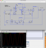
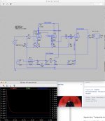
I drew my own schematic from available pics, which corroborates ClefChef's, and also simmed it in LTSpice (screenshot attached), which comes out very close. The signal sine wave looks good and I'd like to try breadboarding it but am worried about that positive grid voltage and the close-to-max dissipation.
* Is the 120V of positive voltage on 6SN7 grid 2 harmful to that triode?
* I calculate the 2A3 to be running at 14W plate dissipation (290 - 43 * 0.057): is this too close to the 15W maximum listed on the RCA datasheet?
I drew my own schematic from available pics, which corroborates ClefChef's, and also simmed it in LTSpice (screenshot attached), which comes out very close. The signal sine wave looks good and I'd like to try breadboarding it but am worried about that positive grid voltage and the close-to-max dissipation.
Attachments
Is that the goal of that cathode follower - to drive the 2A3 grid positive (A2)?
I played with your number some in SE Amp CAD ( not an expert with the program ) and it shows 2A3 responding to it - looks like 5 volts positive gets about an extra 3/4 watt.
I think you're okay to go ahead and breadboard it and give it a listen.
Win W5JAG
I played with your number some in SE Amp CAD ( not an expert with the program ) and it shows 2A3 responding to it - looks like 5 volts positive gets about an extra 3/4 watt.
I think you're okay to go ahead and breadboard it and give it a listen.
Win W5JAG
- Status
- This old topic is closed. If you want to reopen this topic, contact a moderator using the "Report Post" button.
- Home
- Amplifiers
- Tubes / Valves
- Wright Sound WPA 3.5 Power Transformer Replacement Options