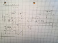
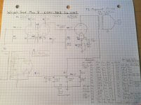
OK, since we seem to be discussing all things Wright schematics, I did up the original WPA 3.5 schemo myself, based on pics I've downloaded, and noticed a couple of errors in the owner-generated schemo I started with. It's awkward, and I'll need to redraw it, but it captures more accurately (1) how the 6SN7 cathode components and the 2A3's 47K grid leak resistor are tied to the negative leg of the final PS cap, (2) how the 2A3 cathode resistor and bypass cap share the PS ground bus, and (3) how the final PS cap connects the entire ground bus to the RCA input ground tab.
I infer that this amp is ultimately grounded through the line preamp via the interconnects.
I infer that this amp is ultimately grounded through the line preamp via the interconnects.
Attachments
Thanks! What's the story behind these incomplete amps?
George lived in my neighborhood. I went to the estate sale when he died.
>
You don't tune the amp for a speaker curve (generally). If the speaker is above 6 Ohms over most of the audio band, you call it "8 Ohms" and pick a transformer to reflect 8 Ohms to what is good for the tube. Triodes are very tolerant.
I realize you are trying to capture "where" wires connect. But sometimes it works better to set Implementation aside and work from Basics.
Your drawing IS good, but confusing me. It helps to know too many schematics so you can recognize basic building blocks and know some good ways to draw them. Also some sturdy conventions for drawing layout.
Small audio usually has one "common" for all power and signal. Chassis, B- cathode returns, RCA jacks.
Tube amps generally have one main B+ for the power tube and some filtered B+ nodes for the small tubes.
This amp appears to have one B-, one big B+, and one small B+.
Draw two horizontal lines, top (B+) and bottom (B-).
Tube stages are usually a string of Rp, tube, Rk. Draw this top to bottom for each tube.
Here, V1a is the basic tube stage, plus that odd 522K resistor from B+ to Rk. V1b lacks a Rp (plate to B+), so draw that and its grid connection. Ah, it is a direct coupled cathode follower.
The little tubes need a cleaner B+ than the fat tube, so there is an R-C network in the B+ rail. While it may physically be with the other power supply parts, for functionality it is clearer if this is shown between little and big tubes.
Sticking with top-down B+ to B-, the 300B's plate winding goes up not down. This IS debatable, because there is SO much going on at a 300B's cathode (filament winding, CT, Rk and Ck, and here a bias for 6SN7 heater) that space gets tight. But I am an old square and I would still draw top-to-bottom. You got plenty graph paper (I approve!) and can find some paste if it runs to another sheet.
Drawn like that, we can see what does what, and what values may be dubious. Fer example, the B+ Plate and Cathode voltages, drawn top-bottom, should make sense. And now I can see and wonder what the 522K is doing here. It adds another half-mA to V1a Rk. (We could get the same bias without the 522K by making 2K into 2.7K.) If we wanted a certain Rk to set audio gain, we might do that. But no, the 47uFd cap takes Rk right out of the audio picture. Also means the 522K can't be any sort of ripple-cancel scheme. It does not make sense as NFB from any point on V1. It does make some sense as NFB from V2 plate, but we don't usually do that with fat triodes (prefering their own hollow NFB), and also I trust your examination. I wonder if it is vestigial from some earlier design. I can't see how one "useless" resistor is any sort of problem. If you found it there, leave it there.
{snip} BUT... I have recently realized that the load impedance ... is *reflected* from the speaker's impedance....
You don't tune the amp for a speaker curve (generally). If the speaker is above 6 Ohms over most of the audio band, you call it "8 Ohms" and pick a transformer to reflect 8 Ohms to what is good for the tube. Triodes are very tolerant.
{snip} how to render the complexities of the actual circuit with the demands for simplicity of the schematic. ... Maybe a different schematic layout would be better....
I realize you are trying to capture "where" wires connect. But sometimes it works better to set Implementation aside and work from Basics.
Your drawing IS good, but confusing me. It helps to know too many schematics so you can recognize basic building blocks and know some good ways to draw them. Also some sturdy conventions for drawing layout.
Small audio usually has one "common" for all power and signal. Chassis, B- cathode returns, RCA jacks.
Tube amps generally have one main B+ for the power tube and some filtered B+ nodes for the small tubes.
This amp appears to have one B-, one big B+, and one small B+.
Draw two horizontal lines, top (B+) and bottom (B-).
Tube stages are usually a string of Rp, tube, Rk. Draw this top to bottom for each tube.
Here, V1a is the basic tube stage, plus that odd 522K resistor from B+ to Rk. V1b lacks a Rp (plate to B+), so draw that and its grid connection. Ah, it is a direct coupled cathode follower.
The little tubes need a cleaner B+ than the fat tube, so there is an R-C network in the B+ rail. While it may physically be with the other power supply parts, for functionality it is clearer if this is shown between little and big tubes.
Sticking with top-down B+ to B-, the 300B's plate winding goes up not down. This IS debatable, because there is SO much going on at a 300B's cathode (filament winding, CT, Rk and Ck, and here a bias for 6SN7 heater) that space gets tight. But I am an old square and I would still draw top-to-bottom. You got plenty graph paper (I approve!) and can find some paste if it runs to another sheet.
Drawn like that, we can see what does what, and what values may be dubious. Fer example, the B+ Plate and Cathode voltages, drawn top-bottom, should make sense. And now I can see and wonder what the 522K is doing here. It adds another half-mA to V1a Rk. (We could get the same bias without the 522K by making 2K into 2.7K.) If we wanted a certain Rk to set audio gain, we might do that. But no, the 47uFd cap takes Rk right out of the audio picture. Also means the 522K can't be any sort of ripple-cancel scheme. It does not make sense as NFB from any point on V1. It does make some sense as NFB from V2 plate, but we don't usually do that with fat triodes (prefering their own hollow NFB), and also I trust your examination. I wonder if it is vestigial from some earlier design. I can't see how one "useless" resistor is any sort of problem. If you found it there, leave it there.
Attachments
Last edited:
George lived in my neighborhood. I went to the estate sale when he died.
That must have been a very somber occasion. I wish I'd gotten into this hobby while he was alive, as it sounds like he was a great guy. Are you planning to complete them? I'd be happy to try and generate a workable schematic that could help.
PRR -- Thank you so much for going through all that. It'll not only help me make better schematics but also think through the circuitry more effectively.
Re: the 522K resistor -- It's funny that every time I post a George Wright schematic, people find some utterly baffling choices that can take up a lot of screen real estate. The 522K resistor has come up in several other fora, and this one at AA has an interesting take on it (read through the couple of followups):
RE: Wright 3.5s - Kyle K - SET Asylum
Paul Joppa of Bottlehead, who knew George well, states that it "looks like it's there to adjust the first stage bias according to the local power line voltage, to stabilize the operating point."
I've posted the original Mono 8 query at the Bottlehead forum as well (Wright Mono 8 Schematic), and the same thing is happening re: the 270 ohm Rp on the 6EM7 2nd plate. I know what I see -- red-violet-brown-gold or 2-7 x10 5% = 270 ohm 5% -- so it's not the usual higher value at that node, but the fellows replying to that thread can't rationalize it even though it's in a pair of live amps that are listened to and enjoyed every day.
I'm not saying they're wrong, of course -- because I wouldn't know -- it's just funny to see how George marched to his own drumbeat and continues to baffle even experienced hands from the beyond.
Correction: I learned that recent Mono 8 pics I had been given were not from the later 6DN7 version of the amp but the earlier (earliest?) 6EM7 version. The silk screening on top of the amp says 5Y3 Russian (indirect heated?), 6EM7, 300B, but the owner is using a 6DN7 because George told him it was a suitable substitute, along wiht the GZ32 or GZ34 for the 5Y3. He bought the amps directly from George in 2001, and they have not been modified.
From what I've been able to gather, the input/driver tube history went from 6EM7 to 6SN7 (the one I'm most interested in) to 6DN7.
Last edited:
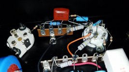
I took a photo of the underside of one of my incomplete Mono 7's. Hope it has something useful.
Hey nerdorama: What does it say on the side of the red "drop" style capacitor between the 6SN7 and 300B sockets?
Well, I'll help you with that if I can. With the other pictures I have it might be possible to figure it out.
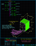
In other news, I just heard back from an engineer at DeYoung, who gave me the specs and a drawing of the DMI 500-7694 PT they used to make for George. The HV winding is 620VCT 100mA. At 310V per side, it confirms my suspicion that the Mono 8 ran at closer to 2A3 voltages.
The drawing also clears up a mystery encountered in the 6EM7 version of the amp, where a light blue and a white/yellow wire from the PT are soldered together on a tab near the PS but are not connected to anything else. Turns out they are legs of the two 2.5V windings, which combines them into a 5V winding for the 300B filament.
It's hard to read, but the two yellow wires are a 5V 2A winding for the rectifier.
Just thought I'd share here.
Attachments
It would be fun to get my mono 7's running. I don't have any transformers so it won't be cheap. The partially finished amps I have are in really nice condition. It's too bad to have them sitting in the shed.
Hi nerdorama. I'd be more than happy to try and generate a schematic for the Mono 7. The colors in your pic are a bit washed out in places. If I were to label them and reattach the image, would you be willing to measure their resistances with a multimeter? It would take just a few seconds and would eliminate any guesswork.
I've asked DeYoung about making a few pair of the PT posted above and am waiting to hear back.
So, I just came across a thread at AA where an owner of a Mono 8 w/6EM7 reports that George said a 6SN7 (among other tubes) could be swapped in place of the 6EM7, but for less gain.
Audio Asylum Thread Printer
It makes me wonder if perhaps George did not substantially change the circuit for the Mono 8 for each "new" driver tube over the years, but kept it more-or-less the same and simply offered it with different input/driver tubes and new silkscreening on the chassis. Do any of you who knew George know anything about that?
Looking back over the images of a Mono 8 w/6SN7 that I posted at the beginning of the thread, with the new knowledge gained in the meantime, it appears the plate and cathode resistors are largely the same as in the 6EM7 model (with maybe a few ohms difference on triode 1 Rk) and that 6SN7 triode2 uses a bypass cap (the little white one that's hard to see) that's not in the 6EM7 model.
A member of the Bottlehead forum suggested a 470uF/10V bypass cap at 6SN7 Rk2. The little white one in the pic says "120" but I can't tell what that pertains to. It looks like a metalized film type rather than an aluminum electrolytic.
Anyway, putting a 6SN7 into the LTSpice model, with Rp1 100K & Rk1 3K | Rp2 27K & Rk2 of 1K, and 323V B+ available to that tube (there's 357V B+ for the 300B), we get:
B+ -- 323V
6SN71 plate/cathode -- 139V/5.5V (1.8mA)
6SN72 plate/cathode -- 177V/5.4V (5.4mA)
Can take up to 0.7V input signal before clipping
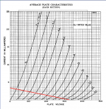
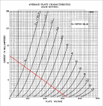
I tried my hand at load lines (attached), which look OK though I'm not sure I did it right.
6SN7 Triode 1:
B+ 323V
Rp 100K
323/100K = 3.23mA
So the line goes from 3.23 mA at 0V to 0mA at 323V. The line seems to match what I get in the model as 1.8mA at 139V. Does that seem correct?
6SN7 Triode 2:
B+ 323V
Rp 27K
323\27K = .0119
Let's round that to 12mA at 0 volts and 0mA at 323V. Likewise, this line seems to match the 177V/5.4mA point on the model.
What do we think about that? Should I get the couple of resistors and caps that I'd need, and do it up on the breadboard tomorrow?
Attachments
Last edited:
Thanks nerdorama, that's much better. It looks identical to the input stage of the WPA 3.5, which is what I have on my breadboard right now but with a 300B output section. I'll start working on this today.
Here’s the (I hope) penultimate draft of the schematic with a parts list for the Mono 8 w/6EM7. I forgot to label the little coupling cap in the 6EM7, so I added it later as C0. Pending feedback, I’ll address any issues in the final version, which will be better scanned and accompanied by spice files.
If I can get a chance this week, I'm going to breadboard the attached circuit with 6SN7s, but with a bypass cap on cathode 2 as seen in the pics of the 6SN7 version originally posted.
In the resistor section of the parts list, MO = metal oxide, MF = metal film, and CF = carbon film.
Attachments
>
You don't tune the amp for a speaker curve (generally). If the speaker is above 6 Ohms over most of the audio band, you call it "8 Ohms" and pick a transformer to reflect 8 Ohms to what is good for the tube. Triodes are very tolerant.
I'm thinking about reflected load on the 300B with my 5K:8ohm OPTs.
5000/8 = 625:1 impedance ratio
Square root of 625 = 25:1 turns ratio
Looking at my speakers' impedance curves (attached), it appears that there are two 25ohm peaks, it's at 5ohms between 140-400Hz, and the rest can be averaged at 10ohm.
So, 10ohm times 25 turns times 25 turns = a reflected load of 6250 ohms
Or, since we’re talking about impedances, you could simply take the impedance ratio of 625:1 and multiply that by the speaker impedance: 625 x 10 = 6250 ohms
Is that correct? If so, that’s a pretty high impedance for the 300B.
The only slots on Western Electric's recommended operating points table that come close to that are:
450V, 40mA, -104V grid into a 6K load (9.5W output)
450V, 50mA, -102V grid into a 6.5K load (9W output)
If I were going by the book, at 6.25K my op point should be right in the middle of those two. And it pushes the tube right to its voltage limit, which is not great.
Or should we just call it a day and go with 8ohms as PRR suggests? That makes the reflected load 5K --- 8 x 25 x 25 = 5000 --- exactly the OPT's primary impedance.
Attachments
Last edited:
The 750R cathode ressistor for the 300B seems too small - if you are sure there is no back-bias used in the design. Also you do not design the amp based on the peaks in the speaker's impedance curve, you should use the nominal value as PRR has already suggested.Here’s the (I hope) penultimate draft of the schematic with a parts list for the Mono 8 w/6EM7.
- Status
- This old topic is closed. If you want to reopen this topic, contact a moderator using the "Report Post" button.
- Home
- Amplifiers
- Tubes / Valves
- Wright Mono 8 Schematic & Operating Points