Let me guess:Netlist said:In counterbalance, the PCB looks cute.
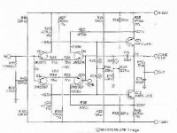
Care to post the schematic?
/Hugo
Attachments
The important thing is that the amp is much faster than 20 kHz (or whatever) and you'll not get any slew rate limiting. So if you have a power bandwidth of let's say 100 kHz and an input filter at 20 kHz you will have a clean response.fotios said:An amplifier is still fast with a rise time of 2 ìsec or with a slew rate of 200V/ìsec at the end.
Slew rate is a parameter you can use for calculating the power bandwidth. The slew rate number alone is not particulary interesting if you don't know the max output voltage.
And the winner is mr QSerraTico_Tico. Bravo! The heart of the module is as presented in the drawing quoted by he. And now it is time to leave you the discussions and you take the solder iron and the breadboard for make it. Place any filter of your preference in the input to make it Line or CD or Phono input. Make tests as me with your inexpensive scope and function generator. It deserves the labour.QSerraTico_Tico said:
Let me guess:
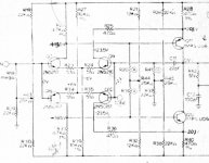
Right. Here is the Bryston.gpapag said:A more clear drawing would surely help a lot.
Regards
George
Attachments
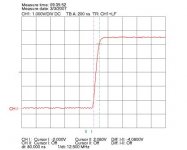
I quote an oscilogram of my generator output, loaded only with his output level pottemtiometer of 1KÙ. As we can see, his rise time is 80nsec. In the future when i will have the posibility to spend money, i will buy a Hewlett Packard generator.janneman said:
This is less than 3V/uSec! Incredibly slow!
Jan Didden
Attachments
fotios said:
I quote an oscilogram of my generator output, loaded only with his output level pottemtiometer of 1KÙ. As we can see, his rise time is 80nsec. In the future when i will have the posibility to spend money, i will buy a Hewlett Packard generator.
Well, if your source has 80nS rise time, and your amp output shows a rise of 6V pp in 2uS, thats 3V/uSec. I don't see how it can be other wise. You typically test slew rate with an input signal that is faster than your amp.
But to be fair, I think your test is somewhere wrong. The amp output does not look as if it is slew rate limited. I have a hunch that you have a lp filter at the amp input that slows down the input signal. If that is so, your measurement is irrelevant and doesn't say anything about the amp. To check slew rate, you should remove the input lp filter.
Jan Didden
janneman said:
To check slew rate, you should remove the input lp filter.
Jan Didden
This makes sense.
Even if you finally will use a LP filter in your amp input.
For example RC = 1.000 Ohm + 220pF, giving limitations of very high frequencies.
Cuts off above ~700kHz
Regards, lineup
Hi,
F(-3db) is predicted with 1/2*Pi*R*C
For 1r0 and 220pF, F(-3db) is about 720MHz.
Unless 1.000 Ohm is supposed to equal 1k0 or =1,000r but that comma confuses because the Continentals use a comma for a decimal point and others use the comma as a 1000s separator, eg 1,200,000=1.2M=1M2
How do we, as a whole earth group, solve this problem?
Sorry to be off topic.
AndrewT said:.
Sorry to be off topic.
.
As usual.
remark to a little detail
when your own math shows that 1.000 Ohm is one thousand ohm
Common sense is good
but only ... when we use it, AndrewT
Like many times before, you prefer to mis-interpret me.
There are besserwissers and there are are besserwissers.
- Some REALLY know better
- other try to make other look foolish .. so they can APPEAR to know better.
Which category fits you, AndrewT, I really dont know.
Maybe we all are a bit of both ....
Not very much Reggards ( you do not have to remark my speling )
lineup
---------------
sqroot ( 2 x pi x 1000 x 0.000000000220 ) = 723431.5596 hertz ~700kHz
for 1.000 Ohm and 220pF
Hi,
This maybe involves some guessing. But this is the only way to handle that.
For instance, I need some forgiving for my bad english.
")
Regards
Jürgen
just by taking the whole thing, as it was meant.How do we, as a whole earth group, solve this problem?
This maybe involves some guessing. But this is the only way to handle that.
For instance, I need some forgiving for my bad english.
Regards
Jürgen
In the input exist only a Hi pass filter at 1 Hz / 12 dB per octave, so it prohibit any d.c. component to enter in the amplifier. A Low pass filter exist in the feedbak loop, around 50 KHz / 18 dB slope. The input has a Zin=100KÙ for Line level use, and the output is preloaded with a voltage divider with ratio 1 : 2 and the R=12KÙ total. The gain is Av=1,5 expressed as an absolute number (not in logarithmic scale in bB!!!!!). Under these all operate the circuit and measured. In real life components, usually the measurements gived with all the input - output - feedback filters or voltage dividers connected. The heart of the circuit is presented from the friend from Brasil. The remain circuitry, is a different story. I have spend 6 months of work to finish the complette circuit. I don't care about slew rate because I DO NOT HAVE THE RIGHT INSTRUMENTS TO MEASURE IT!!!!!!!! But this is not an obstacle TO CONTINUE MY RESEARCH!!!!!!!! Put this in your mind well!!!!! And leave us to LIVE!!!!!!! As WE KNOW, and as WE ARE ABLE!!!!!!!!janneman said:
Well, if your source has 80nS rise time, and your amp output shows a rise of 6V pp in 2uS, thats 3V/uSec. I don't see how it can be other wise. You typically test slew rate with an input signal that is faster than your amp.
But to be fair, I think your test is somewhere wrong. The amp output does not look as if it is slew rate limited. I have a hunch that you have a lp filter at the amp input that slows down the input signal. If that is so, your measurement is irrelevant and doesn't say anything about the amp. To check slew rate, you should remove the input lp filter.
Jan Didden
Enough
Fotios
Have you made any distortion measurements?
If you have a decent sound card in your PC you can use the freeware Rightmark Audio Analyzer
A test result may look like this
If you have a decent sound card in your PC you can use the freeware Rightmark Audio Analyzer
A test result may look like this
I think you miss the point. If you present a scope picture of an amp slewing at 3V/uSec and then say "Wow, what a speed" this is nonsense. Let us see a full swing output, with a very fast input square wave that lets the amp slew limit and then let's see what the slew rate is.
I don't want to take anything away from your accomplishment. As P-A said, it is always a great thing to built something yourself and naturally you are proud of it as you should be.
But if you then present results to us, these results should really show the performance, and not just some uninteresting wave and try to tell us it is special.
Jan Didden
- Status
- This old topic is closed. If you want to reopen this topic, contact a moderator using the "Report Post" button.
- Home
- Amplifiers
- Solid State
- Wow!!! A wonderful preamplifier module!