@analog_sa
When dealing with a CCS to put under a source follower, there is no need to have a very high impedance like you wish to see on an anode. So, according to your experience, I'll replace the DN2535N5 with a IXTP01N100D without cascode. Its Vsg is higher than DN2535N5's, so also its impedance will be higher. But this is to happen not in so close time, I have other things to carry on; it is on my agenda. Thank you for sharing.
When dealing with a CCS to put under a source follower, there is no need to have a very high impedance like you wish to see on an anode. So, according to your experience, I'll replace the DN2535N5 with a IXTP01N100D without cascode. Its Vsg is higher than DN2535N5's, so also its impedance will be higher. But this is to happen not in so close time, I have other things to carry on; it is on my agenda. Thank you for sharing.
FYI - Rochester Electronics shows they have stock of 33,000 pieces of the BF244C JFET.
https://www.rocelec.com/part/FSCBF244C
https://www.rocelec.com/part/FSCBF244C
Thank you, but there is something wrong with them: according to Rochester they are Pb-free and RoHS-compliant, but they are not. I do not care about it, but this is an inaccuracy. The minimum quantity you can order is 740. And they don't fit the Tre, the good ones are BF244B. However, this is not a problem. I have the new PCBs and around the 1st week of December, I'll start to work with the LSK489.

I agree with you, the cascoded CCS is better. Used on top of a plate, or under a differential it is one of the best solutions. I use it in my "fancy" Virtual Battery, it serves 2mA to the zener. But I think it is not worth it when serving 15mA under a source having a very low impedance.I believe this would be a worthwhile change. I have not compared a cascode to a simple CCS in a follower but i have in a differential amp. Preferred, albeit marginally, the cascode.
Scott Wurcer did something interesting with it: https://www.diyaudio.com/community/...erential-or-single-ended-phono-preamp.306811/LSK489
Very nice to have such a part available - thanks Linear Systems. Scott used only +/-15 V for his phono preamp, I would like to use at least double of that (I'd like to swing 30 Vp-p into a power amp with gain = 2). I am planning to build such a preamp to amplify a DAC output, uses resistor I/V. Scott's idea is useful, and he remarked how his preamp produced very low IMD (he used a multitone test to check this).
IIRC the servo in that circuit is acting a bit too fast, I would do something different there.
I haven't checked yet the "excess gate current" for the LSK489 with Vds = 30V. But the part can take up to 60V which is very very nice.
Despite the low transconductance, that circuit I referenced above was able to achieve more than 40dB of gain at DC with only 15V rails and no feedback! What a interesting idea it is.
I think your "fetziklai" should work well, provided the bottom jfet has enough Vds to work with. Normally, a different jfet with a higher Vp would be used for cascoding, like in the buffer by Calvin. https://www.diyaudio.com/community/threads/preamp-buffers-simple-idea.226099/
I think your "fetziklai" should work well, provided the bottom jfet has enough Vds to work with. Normally, a different jfet with a higher Vp would be used for cascoding, like in the buffer by Calvin. https://www.diyaudio.com/community/threads/preamp-buffers-simple-idea.226099/
I promised to return a little after Thanksgiving with the updated “Tre”, but there is always too much to do. So I’m late.
What I can say now is that the LSK489 is touchy a lot! And now I fully understand what our friend @william2001 said about the sensitivity of the DN2535N5: ground yourself while handling these transistors, or you burn them. I burnt some DN2535N5 and I blamed the seller. I burnt some LSK489, and finally understood. Understanding is always important, even when it is expensive.
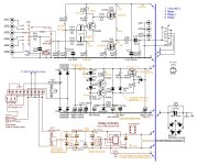
My last post was about the validation of the Cascode/Sziklai configuration. I didn’t post its schematic, and @Alexandre said it should be OK.
It works for sure, Thanks, Alexandre! I was able to test it. All working points are OK. I heard one only channel in my test installation (because of burnt left LSK489), the music flowed across it, but I’m not yet able to say anything about its sound quality.
Now I’m able to post the whole schematic, so the thing is a lot more clear, and ask again:
Do any of you spot any negative points in this Cascode/Sziklai circuit?
What I can say now is that the LSK489 is touchy a lot! And now I fully understand what our friend @william2001 said about the sensitivity of the DN2535N5: ground yourself while handling these transistors, or you burn them. I burnt some DN2535N5 and I blamed the seller. I burnt some LSK489, and finally understood. Understanding is always important, even when it is expensive.
My last post was about the validation of the Cascode/Sziklai configuration. I didn’t post its schematic, and @Alexandre said it should be OK.
It works for sure, Thanks, Alexandre! I was able to test it. All working points are OK. I heard one only channel in my test installation (because of burnt left LSK489), the music flowed across it, but I’m not yet able to say anything about its sound quality.
Now I’m able to post the whole schematic, so the thing is a lot more clear, and ask again:
Do any of you spot any negative points in this Cascode/Sziklai circuit?
Attachments
- Thank you @Alexandre
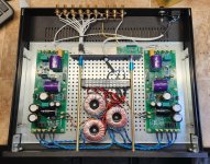
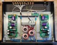
I had some trouble keeping it quiet, but once housed in the cabinet, and connected to the potentiometer it stopped oscillating, so the issue is resolved. It works at its best with R216=8.2KOhm and R217=470Ohm to say 1,2mA across the JFETS, and 2,7mA across the BJT. The sound... I can't be impartial Google "scarrafone rule". To me, it sounds like my hybrid LeGrand at #1, just the sound I was aiming for.
Attachments
What is T212 for? Just curios.I promised to return a little after Thanksgiving with the updated “Tre”, but there is always too much to do. So I’m late.
What I can say now is that the LSK489 is touchy a lot! And now I fully understand what our friend @william2001 said about the sensitivity of the DN2535N5: ground yourself while handling these transistors, or you burn them. I burnt some DN2535N5 and I blamed the seller. I burnt some LSK489, and finally understood. Understanding is always important, even when it is expensive.
My last post was about the validation of the Cascode/Sziklai configuration. I didn’t post its schematic, and @Alexandre said it should be OK.
It works for sure, Thanks, Alexandre! I was able to test it. All working points are OK. I heard one only channel in my test installation (because of burnt left LSK489), the music flowed across it, but I’m not yet able to say anything about its sound quality.
Now I’m able to post the whole schematic, so the thing is a lot more clear, and ask again:
Do any of you spot any negative points in this Cascode/Sziklai circuit?
The LSK489 has a low transconductance, lower than the BF244B in the original project, but obsolete. So to achieve a suitable gain I needed to increase LSK489's transconductance and the best way I could imagine was to add T121 in Sziklai (or CFP) configuration.
So it was time to reopen the project "Tre" without using obsolete components. I saw some of you tried to start the Tre but had to renounce it since the BF244B is tough to find nowadays. I tried to buy some, but I received fakes and BJTs.
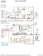
I didn't want to trash this project, because I love it. So here is the °Talia", which uses the LSK489 as the main component. The sound is per my preferences, otherwise I wouldn't post it here.
If some of you still have the components bought for the Tre, they can use almost all of them. No need to use the fancy and expensive Clarity Cap capacitors to achieve good sound.
I've been listening to the Talia for over three weeks and I don't regret the sound of my WOTS LeGrand.
The PCB is reversible and designed to fit HiFi2000's Slim Line 350/1U. Talia is very slim.
If you are interested in this almost easy DIY, if you have some suggestions, please contact me.
If you got bored with this useless "one more post-amplifier", please accept my apologies.
Attachments
I'm glad you like the Talia.
The" Tre", Talia's predecessor, was conceived around the BF244B, no substitutions worked with it. Then BF244B became obsolete, so I had to modernize the schematic to use one of the best suitable components available at this moment. It was quite a job, to have the same "old sound" I'm used to liking.
So this is Talia's project.
I do not have an answer for you (BTW the two components you said are obsolete too), I should put myself to work at the same job I did for the LSK489. You are asking for a new project!
You are here, then supposed to be an electronic expert, so you should be able to carry on the same work I did, then hear the sound and decide if you like it or not, and act consequently.
Following are the hints I can give you:
Current PCB's constraints are as follows:
The" Tre", Talia's predecessor, was conceived around the BF244B, no substitutions worked with it. Then BF244B became obsolete, so I had to modernize the schematic to use one of the best suitable components available at this moment. It was quite a job, to have the same "old sound" I'm used to liking.
So this is Talia's project.
I do not have an answer for you (BTW the two components you said are obsolete too), I should put myself to work at the same job I did for the LSK489. You are asking for a new project!
You are here, then supposed to be an electronic expert, so you should be able to carry on the same work I did, then hear the sound and decide if you like it or not, and act consequently.
Following are the hints I can give you:
- you can use almost any TO220 enhanced mosfet as a follower (I used a depletion here, just for experimentation purposes, and it fits very well);
- you can use a depletion mosfet like the cheap DN2535N5 as a CCS keeping in mind its -1.5Vgs(off);
- R217 imposes the current across the cascode T211 (Id=T12's Vbe/R217);
- you must find the correct polarization by varying R216 and R218, achieving the midpoint voltage at the value you see in the schematic with a 10% tolerance (to be refined in a second step), and last but not least, a sound you like;
Current PCB's constraints are as follows:
- GSD pinout for mosfets;
- LSK489-like pinout for the double JFET;
- other obvious constraints due to the components to buy.
AFAIK when you use a mosfet as a follower, its input capacity is very low. So I neglected mesfets' input capacity reported on their datasheets. Everything works perfectly. We must also consider that 6H30's and paralleled 6922 triodes' plate impedance is very low, so there is no hassle to drive the mosfet. The last version uses the ECX10N10, which today is the best possible power mosfet for audio. This speech is about the LeGrand E2. Talia uses a depletion mosfet as a follower, whose capacity is extremely low.
- Home
- Source & Line
- Analog Line Level
- WOTS Pre-amplifiers