Hi,
Sounds about right...
The problem is, there is much other work to be done on this DAC, I am unsure the OP either can or is willing to do so...
Ciao T
Thorsten can you please check if this is right ?
Sounds about right...
The problem is, there is much other work to be done on this DAC, I am unsure the OP either can or is willing to do so...
Ciao T
mfrimu said:Stormsonic,
Are you saying those NAND gates introduce jitter? I'se seen some products like Monachy Audio DIP (highly reviewed) that use a similar technique to raise spdif levels...
Thanks
@mfrimu
ThorstenL explained very well.
If you still want input buffer for your CS841x receiver, you will need DIY approach. Schematic can be found HERE.
I can't get the schematics, and I'm curious what has been implemented in the circuit.
I have a couple of these on order myself now, if I get more information as a result of that, I'll let you know.
") Looks to me the fastest way to acquaint myself with the WM8805 which over here is priced under $1.5 so really rather a bargain.
Looks to me the fastest way to acquaint myself with the WM8805 which over here is priced under $1.5 so really rather a bargain.Hello,
Thanks for all the suggestions. I purchased this PCB a few years ago and it was at the time the only PCM1704 PCB I could find. I selected the components and built this DAC while enjoying the learning experience and expected the circuit to not be perfect. At that time, all PCM1704 circuits I found were pretty much the same +/- few things.
I appreciate all the input and will implement the buffer bypass and other suggestions shortly. I'm also looking forward for the Cen/Sen/Zen I/V (another thread). I might also test a TUBE output option as I have heard another similar dac with tubes and it sounded noticeably better.
Hi,
Can't do any harm.
The 0.1uF bypasses should be SMD ceramic, placed as close to the IC pins (sodered directly onto them if possible) as possible.
And of course, they should present...
Ciao T
Looking at the PCM1704 datasheet there are quite a few 4.7uf and 47uf capacitors. Therese are about 15mm away from the ICs right now. Should they be closer?
Can't do any harm.
What about the .1uf and 100uF bypass ? Should they be on the PCM1704 daughter board as close as possible?
The 0.1uF bypasses should be SMD ceramic, placed as close to the IC pins (sodered directly onto them if possible) as possible.
And of course, they should present...
Ciao T
Thanks,
Also noticed the TORX178 optical receiver output HIGH is at 4v, too high for the WM8805. I searched but did not find any info on TORX to WM8805 circuits. Seems that Torx178 was made in the times of TTL/CMOS crystal receivers. I'd like to keep an optical in for my video player (not that critical). What resistor(s) should I use to attenuate it?
PS: After removing the Buffer Circuit the WM8805 is working correctly. I'm going for a comparison listening session soon and will report.
Thanks for the help!
Hi,
Try 0.1uF in series and then 680Ohm series and 100R to ground.
Ciao T
Also noticed the TORX178 optical receiver output HIGH is at 4v, too high for the WM8805. I searched but did not find any info on TORX to WM8805 circuits. Seems that Torx178 was made in the times of TTL/CMOS crystal receivers. I'd like to keep an optical in for my video player (not that critical). What resistor(s) should I use to attenuate it?
Try 0.1uF in series and then 680Ohm series and 100R to ground.
Ciao T
Thanks for the Toslink interface advice.
I finnaly got hold of the schematics, attached the wm8805 section. I noticed that there is a 0.1uf in series with each input. Should I then remove all other 0.1 in the spdif path to the receiver as well? I have removed the 75R to ground as one is on the device. At least this circuit has proper bypass caps installed!
Looks like an ok implementation, would have been nice to power the crystal seperately (as some forum members seem to prefer).
Attachments
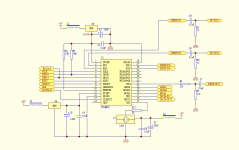
Actually after further inspection with a magnifying glass, the circuit does not implement any resistors/capacitors on inputs. Same for the output. I assume the output is ok to be fed directly into the DF1704 (i2s)
Also there is only one 3.3v supply (regulator) but all bypass caps are in place.
Also there is only one 3.3v supply (regulator) but all bypass caps are in place.
Hi,
Yes.
I personally prefer to keep the 75R at the jack and keep wiring afterwards short low capacitance. But not much you can do there.
Not sure on the "proper" part. But not much you can do on that score.
Really? Now why would you something like that?
Actually, it would have been good to not see a 5V clock signal go into a 3.3V powered device and even worse into an input intended for use with a clock crystal. This is a very, very bad design.
Ciao T
I finnaly got hold of the schematics, attached the wm8805 section. I noticed that there is a 0.1uf in series with each input. Should I then remove all other 0.1 in the spdif path to the receiver as well?
Yes.
I have removed the 75R to ground as one is on the device.
I personally prefer to keep the 75R at the jack and keep wiring afterwards short low capacitance. But not much you can do there.
At least this circuit has proper bypass caps installed!
Not sure on the "proper" part. But not much you can do on that score.
Looks like an ok implementation,
Really? Now why would you something like that?
would have been nice to power the crystal seperately (as some forum members seem to prefer).
Actually, it would have been good to not see a 5V clock signal go into a 3.3V powered device and even worse into an input intended for use with a clock crystal. This is a very, very bad design.
Ciao T
Hi Thorsten, I beg to differ. The WM8805 can have an external clock connected ( but not 5V signals) as described in the datasheet.
I think the way Wolfson describes the possibility of an external CMOS clock is unclear. The way they have put it is that a crystal is preferred when the PLL is used as the PLL needs a a jitter free OSCLK signal for optimum performance.
That would mean that they assume the CMOS clock signal is of lesser quality than the internal crystal driven Pierce oscillator ?!?!
It is comical to see you comment that it is a very bad design while you recommended the very same circuit to me some time ago. I mailed you then with the fact that a 5 V TCXO is used
- Is there any point to add bypass caps to the crystal pins? I don't think there are any.
- There is a 30R in series with crystal, should I chnage that for 3.3v operation or is it adequate?
I will separate the 2 boards to confirm crystal is at 5v.
- for internal spdif wiring (from jack to receiver) what wire is recommended, and wher can i find it (i assume a miniature coax). I have a relay switching from toslink/spdif and the trace from relay to receiver (spdif) has a sord of ground shiled consisting of 2 ground lines separate from the ground plane (on each side). Should I bother wiring a coax instead? Distance is about 5-6cm long.
Thanks
Hi,
Of course external clocks can be used. Just not 5V ones and I would probably even interface a 3.3V one via a coupling cap, some attenuation and a set of bias resistors.
Well, the internal clock is not subject to the 150mV ground bounce in the IC's leadframe and bond-wires, BWTFDIK?
You are correct of course, actually the larger PCB I have has a X-Tal. I still have not found occasion to employ that PCB...
There is of course a fix for the 5V TCXO. Use a Tent Clock run at 3.3V...
FWIW, I have encountered 3.3V IC's which would randomly malfunction if fed with a 5V Clock. Really annoying and EXTREMELY hard to track down...
Ciao T
Hi Thorsten, I beg to differ. The WM8805 can have an external clock connected ( but not 5V signals) as described in the datasheet.
Of course external clocks can be used. Just not 5V ones and I would probably even interface a 3.3V one via a coupling cap, some attenuation and a set of bias resistors.
That would mean that they assume the CMOS clock signal is of lesser quality than the internal crystal driven Pierce oscillator ?!?!
Well, the internal clock is not subject to the 150mV ground bounce in the IC's leadframe and bond-wires, BWTFDIK?
It is comical to see you comment that it is a very bad design while you recommended the very same circuit to me some time ago. I mailed you then with the fact that a 5 V TCXO is used
You are correct of course, actually the larger PCB I have has a X-Tal. I still have not found occasion to employ that PCB...
There is of course a fix for the 5V TCXO. Use a Tent Clock run at 3.3V...
FWIW, I have encountered 3.3V IC's which would randomly malfunction if fed with a 5V Clock. Really annoying and EXTREMELY hard to track down...
Ciao T
Hi,
Yes please. Also consider sticking a big'n'bad 'lytic cap there (I have these 2,200uF/6.3V Sanyo super low Z ones I like for these jobs) with a few Ohm series resistance (if the clock starts up with such a slow rise time on the PSU, so do not), for example 33 Ohm and 2,200uF give a PSU Noise filter at 2Hz.
If the clock is 5V, change the 30R to 220R and connect 430R to ground. Use Thin Film SMD resistors for this divider.
You can also try feeding the clock 3.3V, many work fine this way.
To be honest, this is a really thorny subject. And if you ask ten experts you probably get 15 different answers...
My take, if you terminate directly at the jack, you control external reflections well, but your internal wiring can become a bit of a art.
With the distance you have to bridge and the WM8805 having 1K or 10K input Z (forgot which) just place the termination directly at the Jack and keep the rest low capacitance, no coax or the like, but then again the distance is so short...
Ciao T
Is there any point to add bypass caps to the crystal pins? I don't think there are any.
Yes please. Also consider sticking a big'n'bad 'lytic cap there (I have these 2,200uF/6.3V Sanyo super low Z ones I like for these jobs) with a few Ohm series resistance (if the clock starts up with such a slow rise time on the PSU, so do not), for example 33 Ohm and 2,200uF give a PSU Noise filter at 2Hz.
There is a 30R in series with crystal, should I change that for 3.3v operation or is it adequate?
If the clock is 5V, change the 30R to 220R and connect 430R to ground. Use Thin Film SMD resistors for this divider.
You can also try feeding the clock 3.3V, many work fine this way.
for internal spdif wiring (from jack to receiver) what wire is recommended, and wher can i find it (i assume a miniature coax).
...
I have a relay switching from toslink/spdif
...
Distance is about 5-6cm long.
To be honest, this is a really thorny subject. And if you ask ten experts you probably get 15 different answers...
My take, if you terminate directly at the jack, you control external reflections well, but your internal wiring can become a bit of a art.
With the distance you have to bridge and the WM8805 having 1K or 10K input Z (forgot which) just place the termination directly at the Jack and keep the rest low capacitance, no coax or the like, but then again the distance is so short...
Ciao T
Thanks !
That one will stick outside, does it have to be close? Like 15mm ok? Directly on the crystal Vcc ?
Yes please. Also consider sticking a big'n'bad 'lytic cap there (I have these 2,200uF/6.3V Sanyo super low Z ones I like for these jobs) with a few Ohm series resistance (if the clock starts up with such a slow rise time on the PSU, so do not), for example 33 Ohm and 2,200uF give a PSU Noise filter at 2Hz.
That one will stick outside, does it have to be close? Like 15mm ok? Directly on the crystal Vcc ?
Hi,
This ones does not need to be very close.
For that you have your local decouplers. I personally use 10nF 0603, 100nF 0603, 10uF1206 SMD, 100uF Os-Con on Clocks, sensibly arranged.
Important is not just the big cap, but some form of series resistance to filter noise. You can go fancier with a gyrator etc. I like basic passive though...
Ciao T
That one will stick outside, does it have to be close? Like 15mm ok? Directly on the crystal Vcc ?
This ones does not need to be very close.
For that you have your local decouplers. I personally use 10nF 0603, 100nF 0603, 10uF1206 SMD, 100uF Os-Con on Clocks, sensibly arranged.
Important is not just the big cap, but some form of series resistance to filter noise. You can go fancier with a gyrator etc. I like basic passive though...
Ciao T
- Status
- This old topic is closed. If you want to reopen this topic, contact a moderator using the "Report Post" button.
- Home
- Source & Line
- Digital Line Level
- WM8805 upgrade board (cs8414 pins) - dissapointed