Building a Tube Amp for long term -1.3 - Which features do I need?
It is important to determine the major key points the the desired design. The following points I think are important:
A tube rectifier should always be used in my oppinion. You don't need a start up circuit and you buy in acoustic advantages: Tubes, other that solid state, don't suddenly start or stop at a certain point, the borders are smooth and fluent. Many people found this to be an advantage.
The filtering of the supply voltage should be done with LC-filter, since it's more effective than RC. The first capacitor shouldn't exceed 30uF, greater values could overstress the rectifier tube.
I always prefer complete seperation of the channels, so I planned mono blocks. If you build something from scratch, why not do it the best way possible?
I did not need a source selector or a volume control, this is going to be the job of the passive stage of my old NAD until I manage to build such a thing myself. Everyone who needs those things should consider this from the beginning. It means about 100$ more (ALPS 100k stereo potentiometer: 25$; ELMA 04 6 sources: 75$) that have to be in the budget. Input jacks are classic cinch terminals, output is via banana jacks. XLR is technicaly better than cinch, speakon better than banana plugs - both are not that common in hifi and I don't care for either of them because I don't have the nerve to make new cables, neither the money to buy new plugs without a certain improvement. Do as you like.
I wanted to eliminate electrolytic capacitors from my circuit completly. The produce noticable distortions, have a limitated life span and tend to microphonate. This decision costs bare money because oil-paper- or foil-capacitors are many times as expensive. In my circuit there are - with a tiny exeption explained later - no electrolytic capacitors.
Concerning the material of the case, serveral different oppinions exist, too. There are people who say that metall cases have a negative effect on the sound. I can not explain this phenomenon, but it seems to be reproducable and advocated by many. Those people then go ahead and build a wooden case, full of joy until the first taxi goes by and they can hear the radio in their speakers, so they have to isolate their case with metall again. I render this senseless: I wanted a solid metal case capable of shielding the circuit completely from electromagnetic fields.
It is ideal to build external power supply units. I passed on this to save the money for vases, wires, plugs and jacks. A couple of steel plates are going to seperate the power supply inside the chassis from the rest of the circuit.
Last edited:
Building a Tube Amp for long term - 2 - Circuit
Its a stunt and in most cases not necessary to construct your own circuit from scratch. Thanks to the internet we have access to the ouvre of all the brilliant electro engineers of the last 50 years. Just take the frame points of what you want and start searching. The readers projects corner from Jogis Röhrenbude is a good pool, otherwise Google is your friend, too. Just type in your desired output tubes and SE or PP and only a moment later you have a lot of suggestions at hand. Just chose what looks nicest to you and post your project on diy-audio.com. If the local experts give their OK, you're good to go.
My frame was: KT88 Push Pull, Ultralinear, Tube rectifier, Fixed Bias
The result of my search- and decision process was the circuit from this article. Herbert I. Keroes was one of two people (the other one being Hafler) who invented the ultra linear operation. A man who can do such a thing is pretty much likely to be capable of knitting a nice amp, right? In this case he modified the Williamson circuit and adapted it for KT88/6550. The circuit brings the 6SN7 in gain and phase splitter and the 5V4 into the game. I just accepted that.
First step here was to partially rewrite the drawing so you can read it without problems. The supply network for a preamp was eliminated as suggested in the article. That lead to this.
Following that a few more changes were made:
1. The fuses in the cathode legs were replaced by 10 Ohm resistors. This is said to reduce the overall distortion. Instead there is a fuse between B+ and the center tap of the output transformer and a capacitor from center tap to ground to compensate possible current at fuse blow. The resistors are 1/4W so they act as fuses too.
2. The bias supply was changed. The original circuit had a fix overall voltage which was only divided by a potentiometer. I wanted flexible single regulation, so I simply stole one from a quite similar plan from John Eckland (which is by the way recommended if you want to build this amp with toroidal OPTs).
3. By inserting a voltage divider the heaters were referenced to +25V. All the heater pins got a 1nF ceramic capacitor referenced to the chassis. This was suggested in the diy-audio-forum, too; the idea originates from Thorsten Lösch. Someone doubted if this would help my circuit at all, but its not expensive and won't harm anyone.
4. An idea from Thorsten Lösch is also the concept that one should protect a toroidal power transformer from the DC parts in the power net. Because I always use toroidal transformers in the power supply, I adapted his DC-blocker containing of a network of silicium rectifier diods and electrolytic capactiors (the only elcos in my build).
5. And yet another thing from Lösch: He recommends to separate the signal ground from earth and chassis by a network of antiparallel diods. As soon as a serious current appears, the diods start conducting. Under normal conditions they don't conduct, which reduces the danger of hum. This would propably not be certified for a commercial product, but that are the advantages of doing it yourself.
These changes lead to this circuit drawing:
An externally hosted image should be here but it was not working when we last tested it.
Last edited:
Building a Tube Amp for long term - 3 - Choosing the Components
3.1 Output Transformers
The OPT is a transformer that makes the signal suitable for the speakers. It is the bottle neck of the construction and therefore a quality determinating element. The selection shure isn't simple. The actual problem is of course not he spendig of money but the deciding, who to give the money to, means: To determine the value of the offered products. I fought with myself, was hooked on Sowter Inc. for quite some time, but then decided for O/Netics (contact), a small company from Washington, that some people were very satisfied with. Good transformers are made e.g. by Reinhöfer, Retro Sound, Trafo-Baule, Leszek Ogonowski, Welter, Jan Wüsten, Rondo Müller, Amplimo, AE Europe, Tribute, Majestic Inc., Plitron, Lundahl, Hashimoto…..
3.2 Power Transformer
I can only recommend toroidal transformers. In Germany, it is best to take Jan Wüsten on his offer. The quality is good, prices are fair and contact is awesome (help and correction of mistakes inclusive). I'm pretty shure he's selling products of Rondo-Müller, who have a very good reputation.
3.3 Coupling capacitors
Another essential component is the capacitor that couples the signal to the next stage. The best ones are supposed to be the teflon ones the Russians made for their soldiers to tape to their rifles. Or something. Next is polystyrol. After that, the field gets a little blurry. Some swear on silver micas because they basicaly dont microphonate at all. Other like tin foil. The next ones want to leave the country and live of cranberry candy but tell you when asked that they'll rather choose MKP. Teflon caps are expensive, as are boutique parts like Munsdorf, Jensen and whatnot. At 8 pieces that I needed it is not that little money we're talking about. The budget-oriented me was pretty much stuck with the polystyrol caps i got from Oppermann Electronics. Because of the maximal available capacity i had to parallel a few, but with around 1,50$ per finished unit they were still a bargain.
The assembling and sealing of those caps is shown later.
3.4 Filter components
Basicly every one of the above mentioned manufactorer of transformers makes chokes too. I can again only recommend what Jan Wüsten sells: It's made pretty roughly but amazingly cheap. The quality of a choke is not a real factor. For the caps I was left to choose between paper-in-oil or foil. The pricing was quite equal. Foil is technicaly better and more compact, so I went with those. My court purveyor Wüsten stocks both types. A little tip:
If the voltage doesn't exceed 450V, you can use motor run caps (in Germany very cheap from Darisus). Those are MKP caps too and are widely recommended for power supplies. I had bought a few but settled for audio foil types too, because they are rather big.
3.5 Resistors
What certain types of resistors do or dont do seems to be another case of magic noone realy seems to understand. The legendary Howards Dumble once said in an interview one should stick to carbon composite resistors - so I did. My good supplier Wüsten has a wide range of NOW Vitrohm resistors, which I chose. Only for the resistors which were required to be matched I used 0,1% tolerance precision metal film resistors, which I ordered from Conrad with other side stuff.
3.6 Tubes and Sockets
There are only a hand full of factorys still alive making tubes. Besides that a giant pool of NOS (New Old Stock) tubes is available.
The most new stuff either comes from Reflektor (Gold Lion, Electro Harmonix, ...), from JJ or from China. The quality follows that order too. Reflektor seems to be building pretty good tubes with close to zero error rates and amazingly nice sound. Because the Gold Lion reissue is said to be basicaly the same as the Electro Harmonix, but is much more expensive, I chose EH.
Sockets you can basicaly get anywhere. I needed exclusivly octal sockets and found ceramic ones with gold plated contacts at Tube Town für about 3 bucks a piece. Gold plated contacts are desirable because the dont oxidate.
3.7 Wire, Jacks, Cases
Also from Tube Town I got Hammond cases. Those come in many different sizes, two colors and are realy cheap. I don't know any alternative in that price range. You can take basicaly everything you want as your jacks, gold plated is recommended again. I'm using Neutrik cinch terminals and banana terminals from Dynavox. Wiring is done with solid core 1mm² copper wire. Nothing fancy.
Building a Tube Amp for long term - Sealing the Coupling Capactitors
I already wrote a piece about coupling caps. Since they are directly in the signal path, their quality is crucial. It directly affects the sound of the amp, so one is well off thinking about the choice. Though teflon is said to be the best dielectric, a close second is polystyrol. I got 40 pieces 47nF Styroflex caps from Opperman for overall 14$. My circuit specified 250nF coupling caps, so I had to parallel five and seal them. With 1,325€ for five pieces the price was a strong argument for this solution, since teflon caps cost about ten times as much at the moment.
The cardboard roll from the tin foil package volunteered as container (sawing them into equal and straight pieces is much harder than it looks!). Sealing material is pure bee wax. At this time of the year every supermarket carries candles out of it. Price for the wax sufficient for 8 units: 3$. It has the advantage of being completely untoxic, readily available, easy to work with and exellently isolating. "Cera Flava", the scientific term of bee wax, has been used for a long time in electotechnics with good success.
I melted the wax i a small bowl I made out of tin foil in boiling water. The bottom side of the card board roll was closed with a little piece of cardboard glued to it.
All in all one coupling cap costed me 1,64€ (about 2$). A bargain, I'd say.
Pictures:
This looks a little like nuclear warheads I've seen on photos. That has a certain que ne sais qua....
Granulating the wax speeds up the melting process
Empty bottles are good holding devices
Bee wax melts at about 60°C, so it doesn't damage the components. And it smells good too.
I already wrote a piece about coupling caps. Since they are directly in the signal path, their quality is crucial. It directly affects the sound of the amp, so one is well off thinking about the choice. Though teflon is said to be the best dielectric, a close second is polystyrol. I got 40 pieces 47nF Styroflex caps from Opperman for overall 14$. My circuit specified 250nF coupling caps, so I had to parallel five and seal them. With 1,325€ for five pieces the price was a strong argument for this solution, since teflon caps cost about ten times as much at the moment.
The cardboard roll from the tin foil package volunteered as container (sawing them into equal and straight pieces is much harder than it looks!). Sealing material is pure bee wax. At this time of the year every supermarket carries candles out of it. Price for the wax sufficient for 8 units: 3$. It has the advantage of being completely untoxic, readily available, easy to work with and exellently isolating. "Cera Flava", the scientific term of bee wax, has been used for a long time in electotechnics with good success.
I melted the wax i a small bowl I made out of tin foil in boiling water. The bottom side of the card board roll was closed with a little piece of cardboard glued to it.
All in all one coupling cap costed me 1,64€ (about 2$). A bargain, I'd say.
Pictures:
An externally hosted image should be here but it was not working when we last tested it.
This looks a little like nuclear warheads I've seen on photos. That has a certain que ne sais qua....
An externally hosted image should be here but it was not working when we last tested it.
An externally hosted image should be here but it was not working when we last tested it.
Granulating the wax speeds up the melting process
An externally hosted image should be here but it was not working when we last tested it.
An externally hosted image should be here but it was not working when we last tested it.
Empty bottles are good holding devices
An externally hosted image should be here but it was not working when we last tested it.
Bee wax melts at about 60°C, so it doesn't damage the components. And it smells good too.
An externally hosted image should be here but it was not working when we last tested it.
An externally hosted image should be here but it was not working when we last tested it.
An externally hosted image should be here but it was not working when we last tested it.
An externally hosted image should be here but it was not working when we last tested it.
An externally hosted image should be here but it was not working when we last tested it.
Building a Tube Amp for long term - 4 - Casework
However your individual case looks, most of the people won't get a readily drilled case for their project. That means that after you've decided on your layout (I'm going to explain the important parts to that in the next article), you have to start drilling and cutting the holes for the sockets and terminals. A few basic tips may safe you a lot of pain:
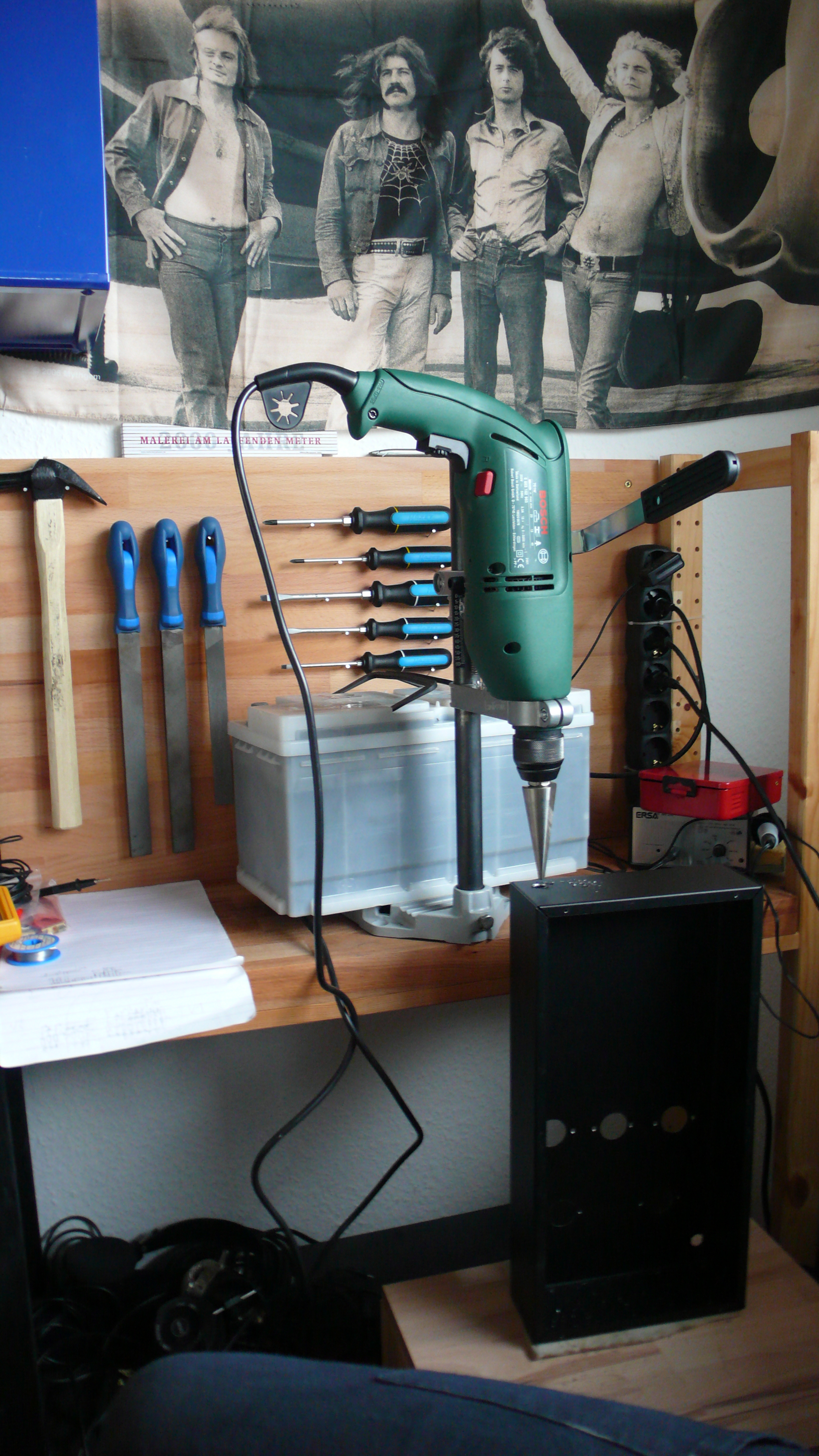
You should drill the holes using a standing dilling machine and a specified hole cutter. Usual drills will never give you such a clean round hole. Besides, you are going to need holes in strange dimensions for which you wouldn't even get a drill. Since hole cutter are conical they can produce any diametre. You should always drill from the side that is later visible.
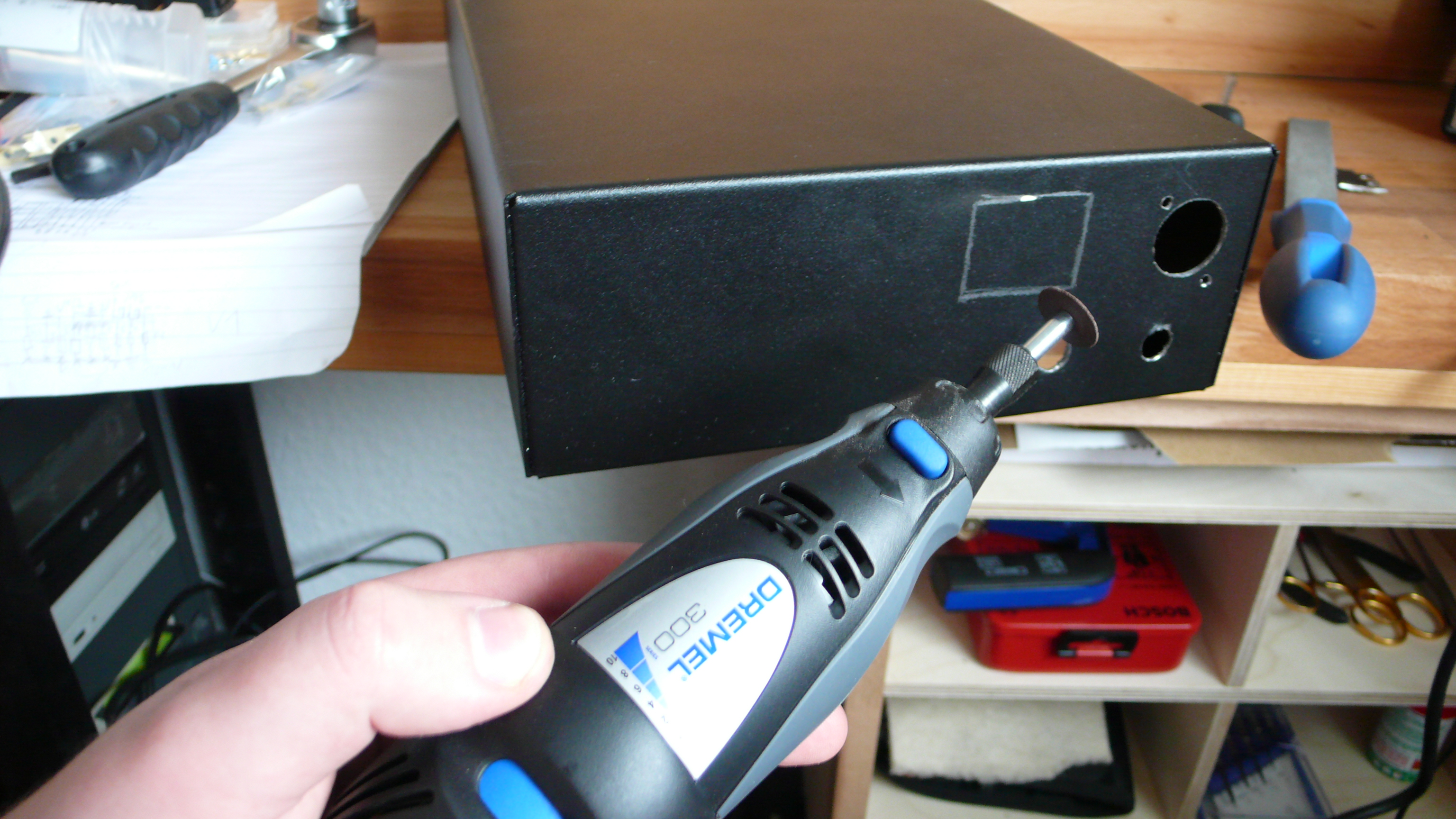
For making square holes you should use a Dremel tool. My holes are relativly ugly since I didnt use such a tool for quite some years. A few minutes of practice and they would have been nicer. A Dremel can usualy be found at someone you know.
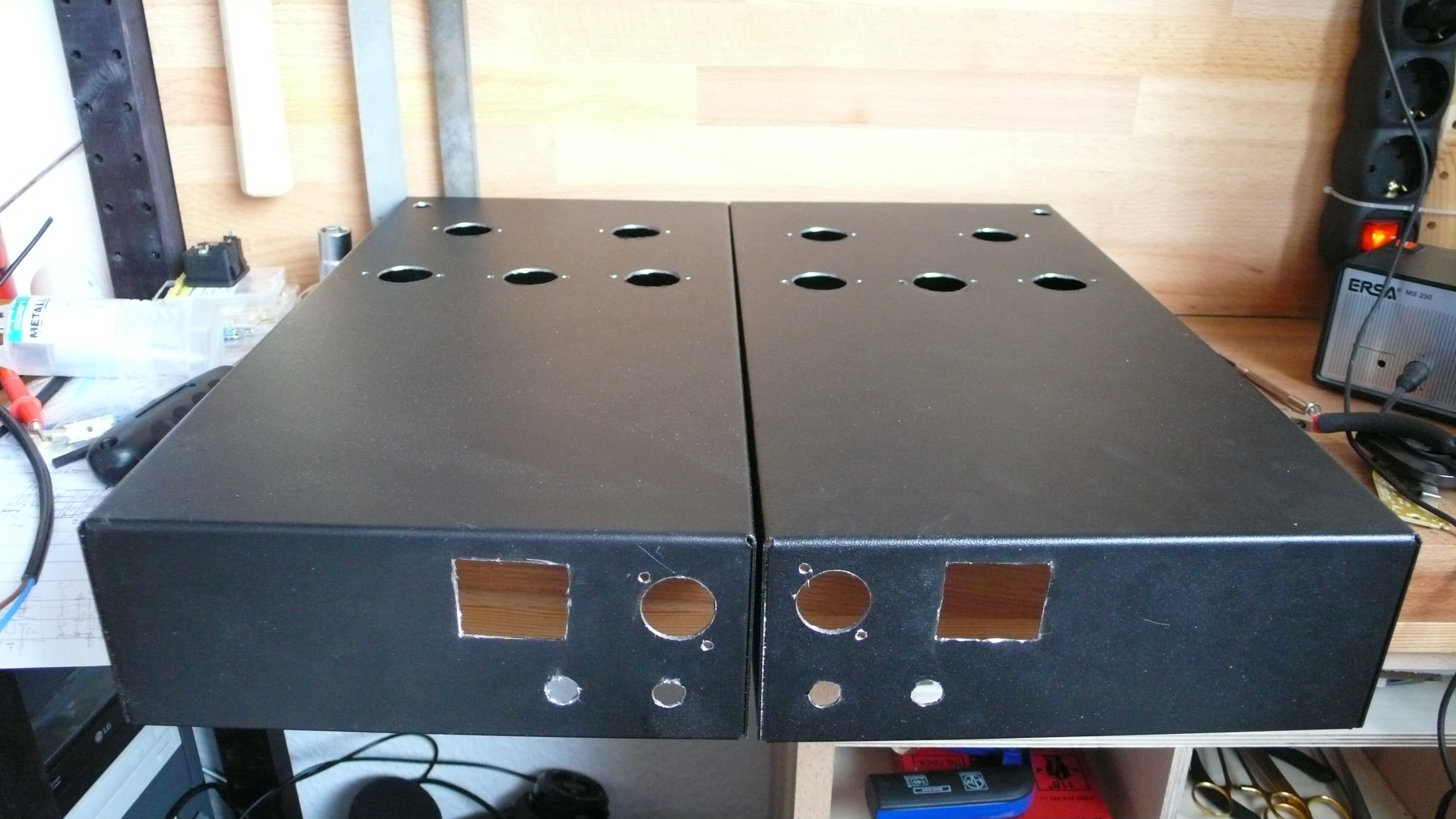
A rule I always ignore and keep paing the price for is that whenever you work on your case you should cover it up with masking tape. You can see from the pictures that I was uncautious and got myself quite a few scratches. I'm going to have to try polishing those away.
You can best write you cutting and drilling marks directly on the case with a soft pencil.
Being the constant victim of my circumstances I had to make use of what I could get my fingers on. In this case in the form of a wolfcraft power drill stand thingy. You should realy keep away from those. Thanks to this thing, the holes are precisly within only a few inches.
A Dremel tool is undispensible
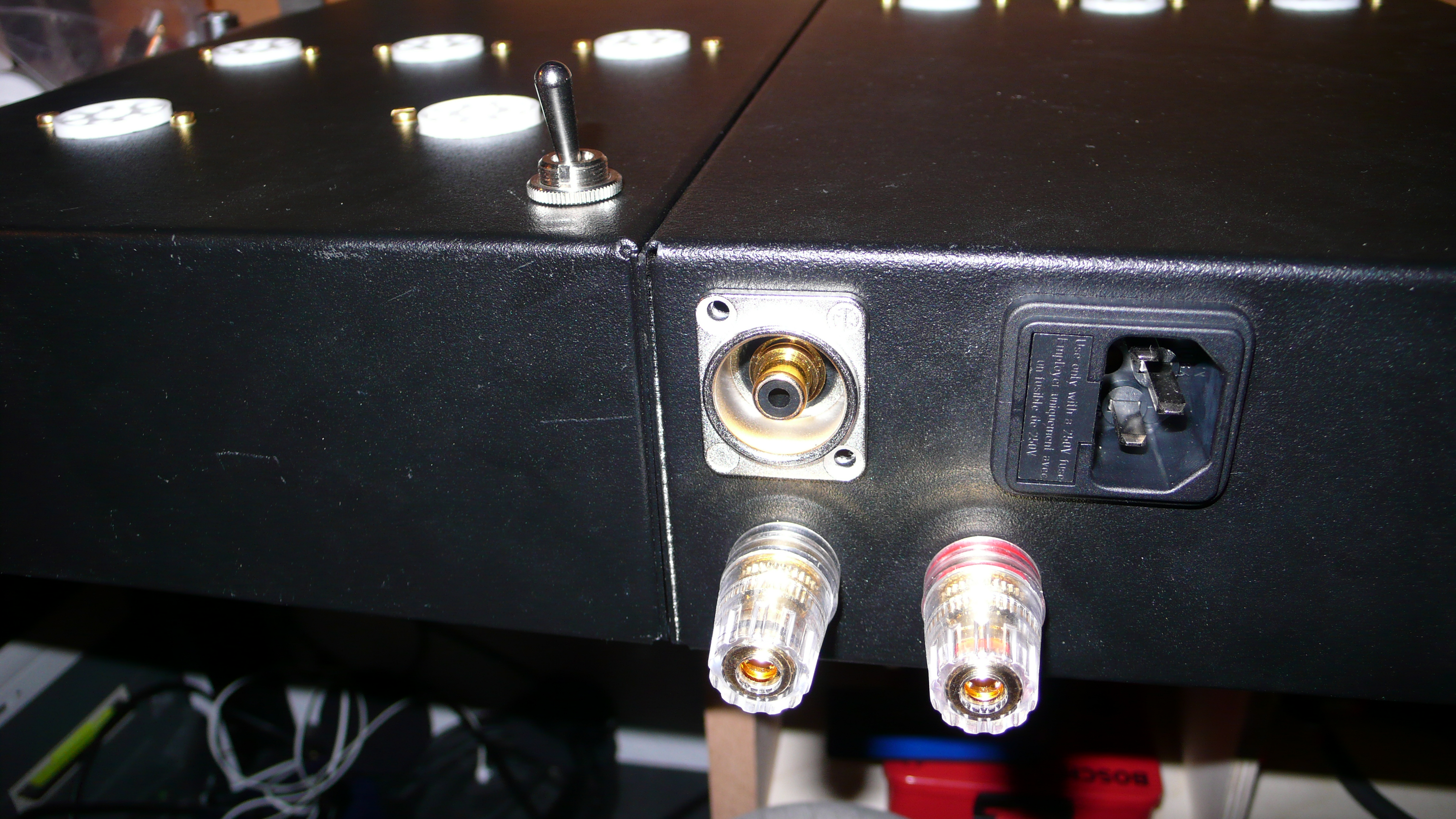
Lucky me that you don't see the holes in the end. The power connectors are glued in later on.
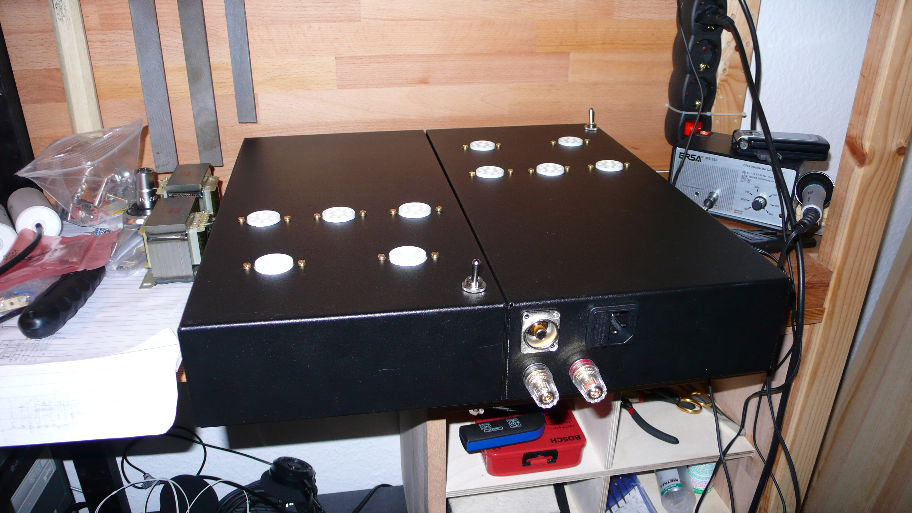
The actual mounting of the components is done quite quickly. Screws are brass because gold and black just looks kick ***. Brass is quite sensitive, which means that the holes have to be well deburred. The screws of the cinch terminals are still missing.
I will post pictures of the reenforcement and shielding plates as soon as they arrive here...
If you are afraid of doing these things - I can understand you. But you should at least know someone with manual skills who can help you for a crate of beer or something. If you work concentratedly, you can manage to do this casework within one hour.
However your individual case looks, most of the people won't get a readily drilled case for their project. That means that after you've decided on your layout (I'm going to explain the important parts to that in the next article), you have to start drilling and cutting the holes for the sockets and terminals. A few basic tips may safe you a lot of pain:
You should drill the holes using a standing dilling machine and a specified hole cutter. Usual drills will never give you such a clean round hole. Besides, you are going to need holes in strange dimensions for which you wouldn't even get a drill. Since hole cutter are conical they can produce any diametre. You should always drill from the side that is later visible.
For making square holes you should use a Dremel tool. My holes are relativly ugly since I didnt use such a tool for quite some years. A few minutes of practice and they would have been nicer. A Dremel can usualy be found at someone you know.
A rule I always ignore and keep paing the price for is that whenever you work on your case you should cover it up with masking tape. You can see from the pictures that I was uncautious and got myself quite a few scratches. I'm going to have to try polishing those away.
You can best write you cutting and drilling marks directly on the case with a soft pencil.
Being the constant victim of my circumstances I had to make use of what I could get my fingers on. In this case in the form of a wolfcraft power drill stand thingy. You should realy keep away from those. Thanks to this thing, the holes are precisly within only a few inches.
A Dremel tool is undispensible
Lucky me that you don't see the holes in the end. The power connectors are glued in later on.
The actual mounting of the components is done quite quickly. Screws are brass because gold and black just looks kick ***. Brass is quite sensitive, which means that the holes have to be well deburred. The screws of the cinch terminals are still missing.
I will post pictures of the reenforcement and shielding plates as soon as they arrive here...
If you are afraid of doing these things - I can understand you. But you should at least know someone with manual skills who can help you for a crate of beer or something. If you work concentratedly, you can manage to do this casework within one hour.
Building a Tube Amp for long term - Presenting O/Netics Output Transformers
As I've already written before: Choosing an Output Transformer wasn't too easy. I had decided that I wanted to buy something good and not haggle for the last buck, because the quality of these components are realy important. There are quite a few choices, AE and Tribute from the Netherlands make highend stuff, Hashimoto, Tamura and Lundahl are available and I too could have gotten my hands on Sowter. Plus, there are a lot of regional names it's even harder to rank.
Via the diy-audio.com-forum I stumbled over Bud Purvine (BudP) of the little company O/Netics (contact), located in Washington. All he said sounded very well-informed and elaborated, his products got very good reviews. What made the decision in the end was that I very much respect people who take time to help other people without pointing a giant finger on their own products all the time. The contact was very comfortable and nice - Bud didn't recommend the most expensive out of his programm, but the least. That was another point on the positive side.
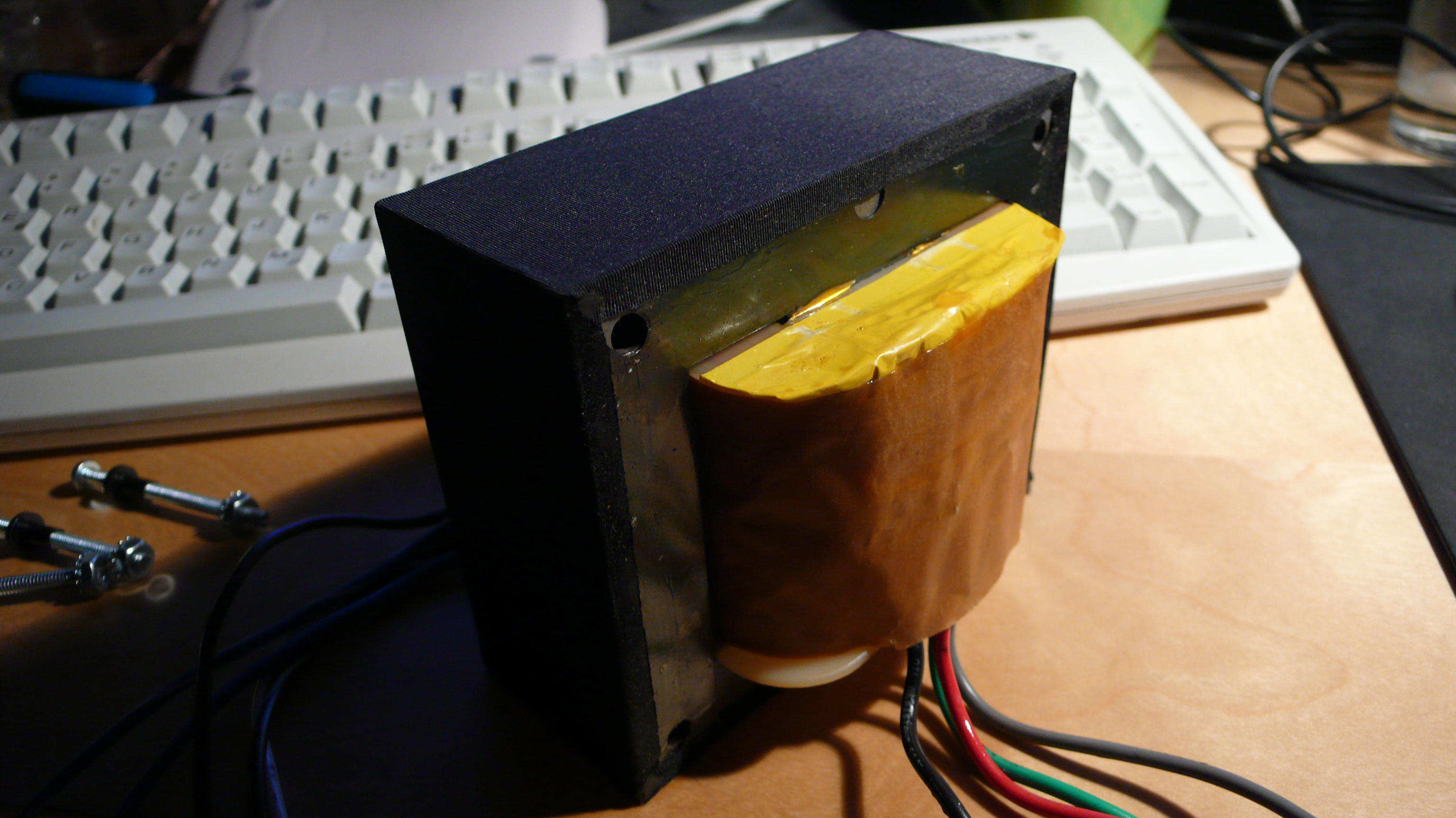
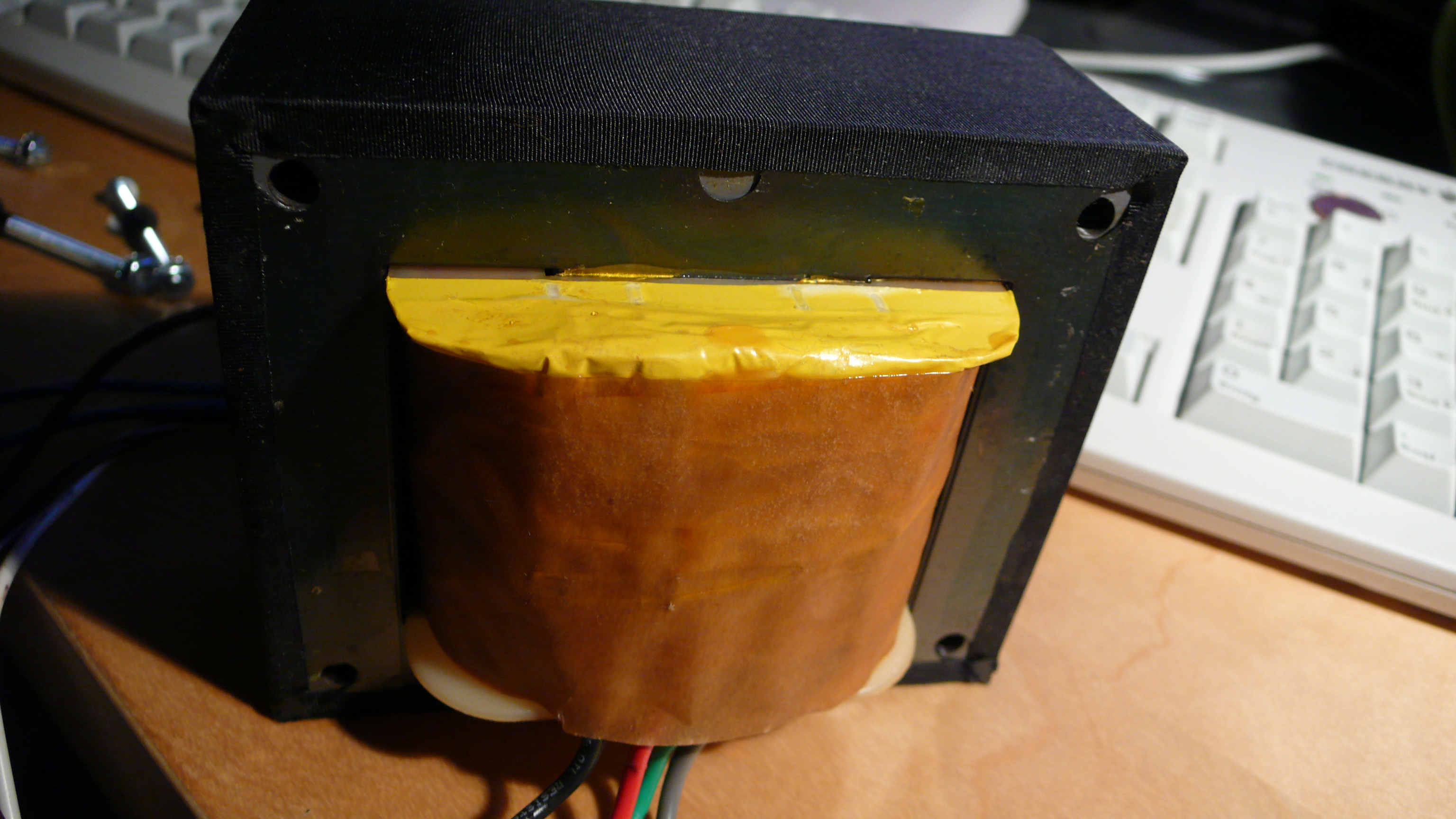
The transformers come in different levels of quality, with the next level roughly costing twice as much as the last one. I picture this to be a little bit like the complications in watch making, more complex arrangement of the dielectric materials, more complex winding and better core material, it all costs money. I decided for the second of three offered grades, so that the little get-the-best-man in my head would shut up. More I just couldn't afford, since shipping to Germany also adds a hundered bucks. Bud predicted 8 weeks for production and hit that date almost to the day - if you are used German craftsmen, that's a very refreshing change.
The OPTs were wound to my specifications for KT88 in push-pull with ultra-linear-taps. With 100W they are sufficently oversized. Core material is M3 silicon steel, Bud intentionaly passes on amorphous cores, which he explains very intensivly here. Other companys like Hashimoto don't use amorphous cores for the same reasons. The winding bobbin is, different to other high end winders, plastic and not cardbooard.
Regarding that Bud wrote me this:
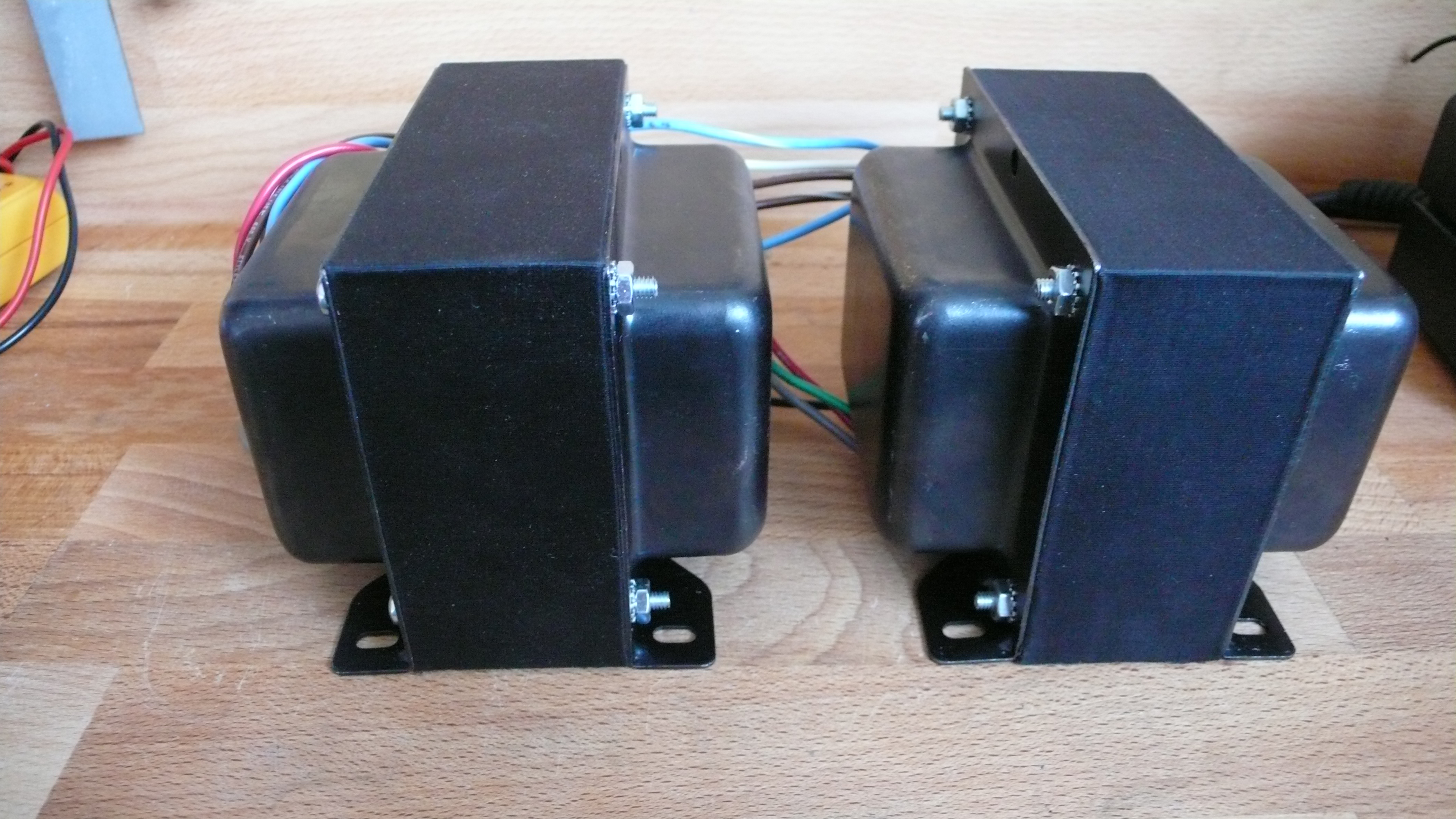
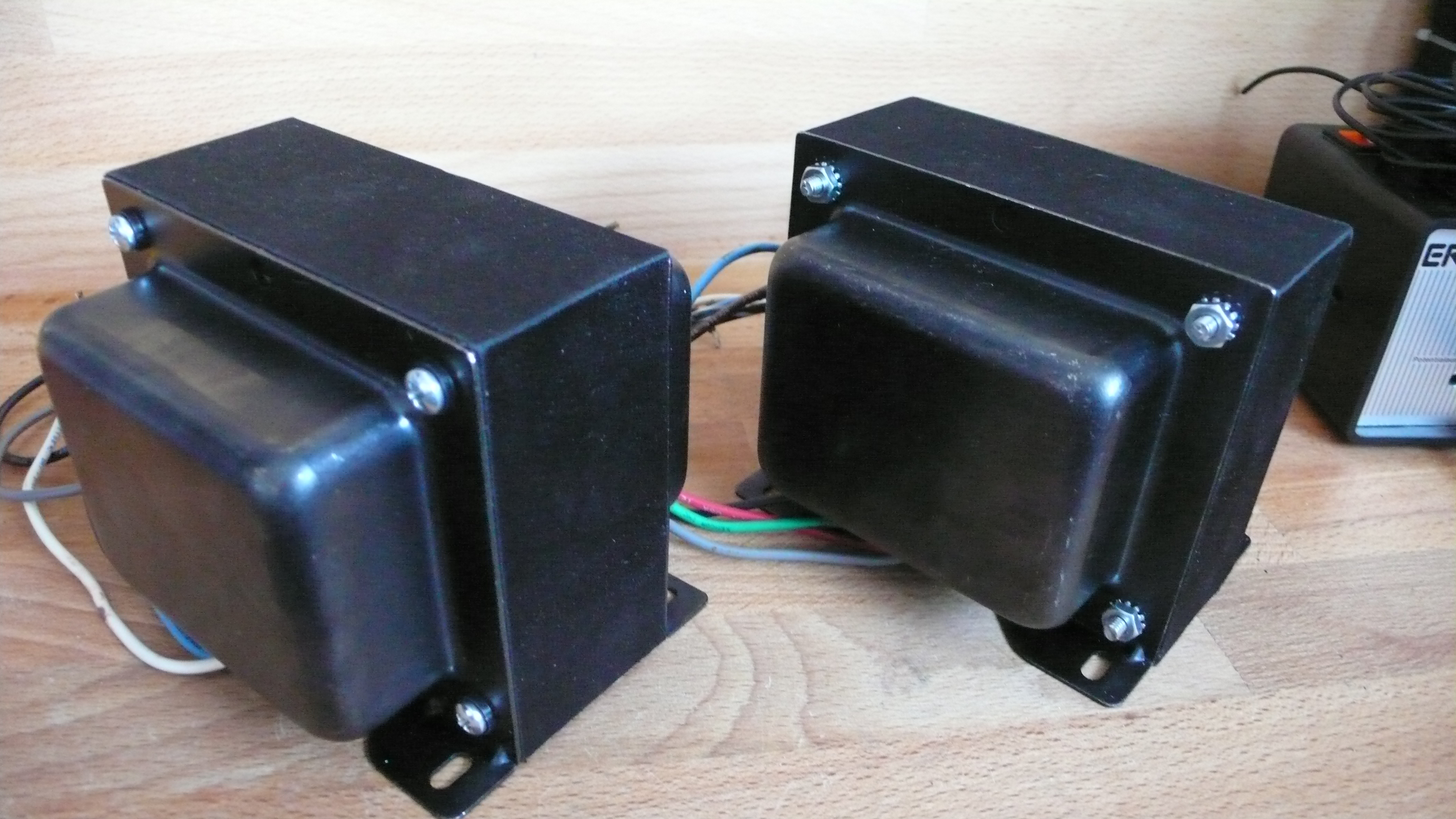
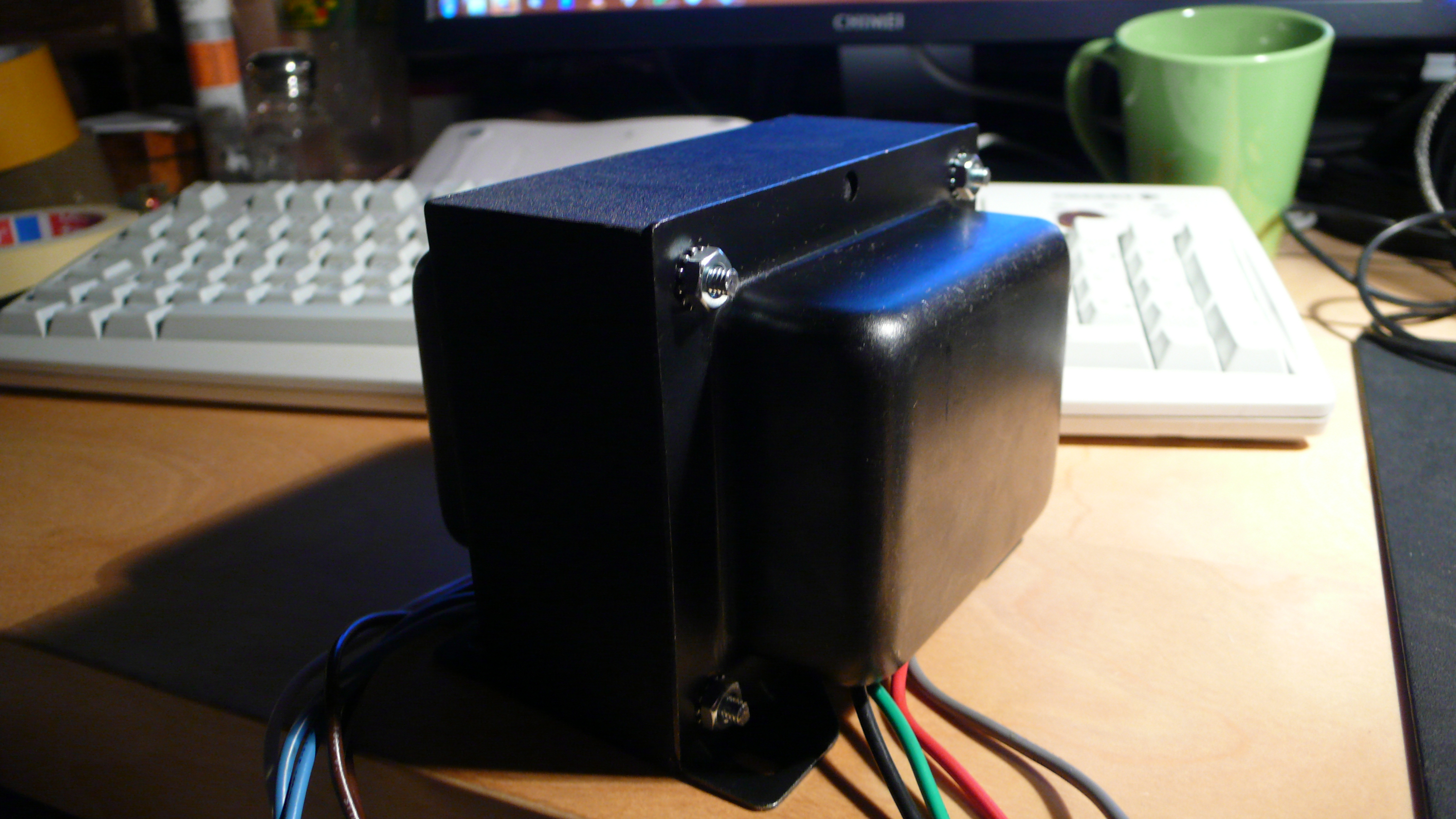
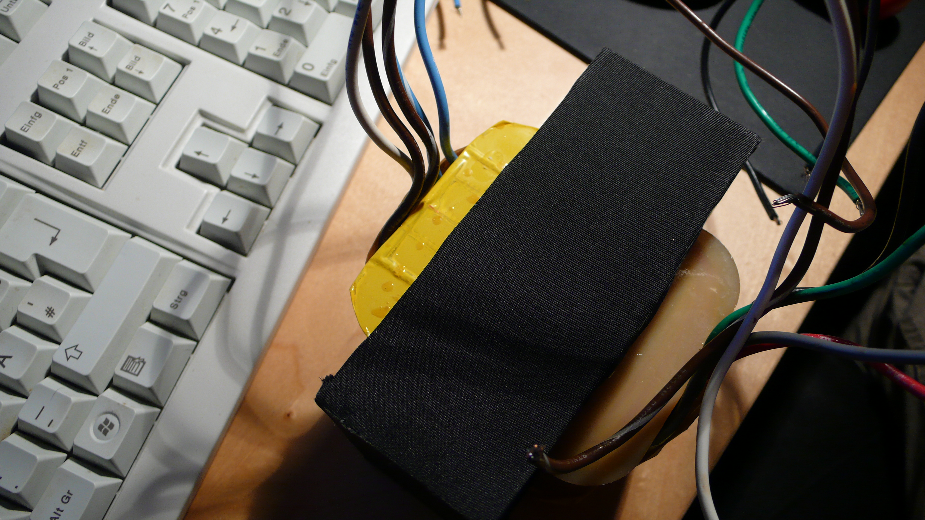
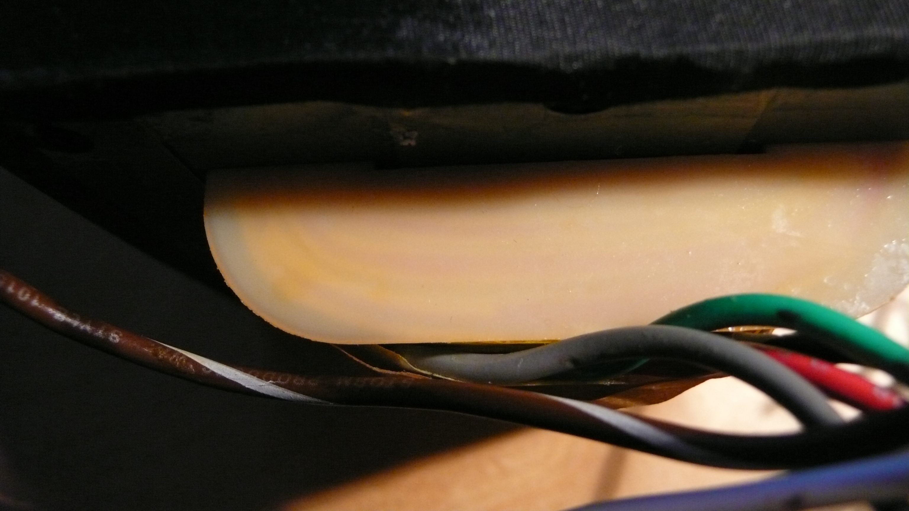
Now a few pictures of the OPTs as they come out of the box. The bells are intended to be painted. I find the textile covering of the core worthy of noting, they are quite - do I dare to say it? - sexy.

As I've already written before: Choosing an Output Transformer wasn't too easy. I had decided that I wanted to buy something good and not haggle for the last buck, because the quality of these components are realy important. There are quite a few choices, AE and Tribute from the Netherlands make highend stuff, Hashimoto, Tamura and Lundahl are available and I too could have gotten my hands on Sowter. Plus, there are a lot of regional names it's even harder to rank.
Via the diy-audio.com-forum I stumbled over Bud Purvine (BudP) of the little company O/Netics (contact), located in Washington. All he said sounded very well-informed and elaborated, his products got very good reviews. What made the decision in the end was that I very much respect people who take time to help other people without pointing a giant finger on their own products all the time. The contact was very comfortable and nice - Bud didn't recommend the most expensive out of his programm, but the least. That was another point on the positive side.
The transformers come in different levels of quality, with the next level roughly costing twice as much as the last one. I picture this to be a little bit like the complications in watch making, more complex arrangement of the dielectric materials, more complex winding and better core material, it all costs money. I decided for the second of three offered grades, so that the little get-the-best-man in my head would shut up. More I just couldn't afford, since shipping to Germany also adds a hundered bucks. Bud predicted 8 weeks for production and hit that date almost to the day - if you are used German craftsmen, that's a very refreshing change.
The OPTs were wound to my specifications for KT88 in push-pull with ultra-linear-taps. With 100W they are sufficently oversized. Core material is M3 silicon steel, Bud intentionaly passes on amorphous cores, which he explains very intensivly here. Other companys like Hashimoto don't use amorphous cores for the same reasons. The winding bobbin is, different to other high end winders, plastic and not cardbooard.
Regarding that Bud wrote me this:
I am using the chopped glass fiber filled Nylon bobbin as the basis for creating a dielectric circuit. There are two wraps of Mylar film, 0.005″ thick that are the final wrap. Within this enclosure, made of material with a dielectric constant of 3.5 are windings that are potted with a polyester resin also with a dielectric constant of 3.5. At the antenna barriers, from primary to secondary, you would find a Nomex / Mica paper dielectric barrier with a dielectric constant of 2.2. Building in this fashion forces the motile electrons out of the primary and secondary winding bodies and causes them to accumulate at the antenna barrier instead. This in turn allows for a much more complete E Field information transform across those barriers. This is that odd “charging” period you are about to experience. I do this to force the transformer to retain and transform more information than a typical audio transformer will allow.This combined with our core construction method that provides a large measure of passive demagnetization for after a B Max saturation point allows the core to track the back half of the wave form, rather than sit in saturated polarization until an opposite H force is applied. Transformers built in this fashion have no crossover distortion and are flat i phase and frequency response to beyond 40 kHz at any power level. I do mean flat, + / – 0 db from 20 to 40 kHz. They also have smooth impedance characteristics below 20Hz and will not oscillate, ever.
Now a few pictures of the OPTs as they come out of the box. The bells are intended to be painted. I find the textile covering of the core worthy of noting, they are quite - do I dare to say it? - sexy.
Last edited:
Ok, the first block is build, which brought the first problems my way.
I powered the amp up (of course with a load at the opt).
Actualy I wanted to bias the amp and was frightend finding 1V across my 10R cathode resistor. So I checked the bias voltage and its -75V at first (between grid and gnd), as it's supposed to be, then, after a couple of seconds after powering up, it gets positive (!) and then drops back to about -35V, which obviously is too much.
Also, after inital 550V between B+ and gnd, the voltage drops very quickly to about 405V.
I double checked everything I could think of, but I can't find any wrong wiring.
Can you help me?
If you built the amp as in #62, you will notice a DC link between the output stage grids (neg) and the driver anodes. (Ignoring all the RC constants for a moment) The 6SN7 may have a slightly slower warm up time that of the rectifier. This allows a higher positive voltage against the negative grid volts which the o/p stage grids see (i.e high instant Iquies). On switch on, the neg volts will be near instantaneous, so you will get o/p stage cathode currrent fluctuations till the driver anode volts is settled down. Some o/p tubes can accept this kind of unsettled surge, some not and can strain the screen grids.
I assume you are using the correct indirectly heater rectifier, 5V4.
IMO I am against circuits of this type exactly for the reason outlined above.
richy
I assume you are using the correct indirectly heater rectifier, 5V4.
IMO I am against circuits of this type exactly for the reason outlined above.
richy
Thanks. Yeah, I'm using a GZ32, which should electricly be exactly the same.
If it is like you say, shouldn't the problem disappear some time in? (Or was i just not patient enough?) Btw. shouldn't it be there at all when the input tubes are not plugged in? Or are 35V already the steady state voltage that crosses that 470k resistor?
If it is like you say, shouldn't the problem disappear some time in? (Or was i just not patient enough?) Btw. shouldn't it be there at all when the input tubes are not plugged in? Or are 35V already the steady state voltage that crosses that 470k resistor?
Well, I disconnected the resistor parallel to the coupling cap and the problem went away. It slowly dawns on me, that Keroes took this 35V into account, describing a 117V prim voltage for the bias supply.
Well, nevertheless, previously my tubes were biased too high, now they are too low. Literaly. With the pot fully turned towards earth, I get 10mA bias current. (Thank you John Eckland...) Well, I'm a little stuck between the sheets now...
Well, nevertheless, previously my tubes were biased too high, now they are too low. Literaly. With the pot fully turned towards earth, I get 10mA bias current. (Thank you John Eckland...) Well, I'm a little stuck between the sheets now...
Well, I had the first one up a couple of hours now and I have to say that it sounds exeptional. Realy good. And Bud Purvine warned me that the OPTs would around 40 hours of break in. If the sound is going to improve even more, I don't know... I think I'll have to work on my face.
The one things thats bugging me is pretty noticeable noise. It's definitly no hum, but very consistent noise (buzz?). I tried moving around the wires, I tried moving the attachment of the heater bias to a higher filtered stage of the PSU, but none of this helped. I'm yet to try the NFB loop, but was lazy and scared after the first try which resulted in motor boating, so unregardless of my thinking, the output tubes are exactly the wrong way around at the OPT i guess, aren't they?
Well, still, the noise shouldn't be there anyway. Any tips? Could this be related to my disconnecting of the resistors paralleling the coup caps for RC time change?
face.The one things thats bugging me is pretty noticeable noise. It's definitly no hum, but very consistent noise (buzz?). I tried moving around the wires, I tried moving the attachment of the heater bias to a higher filtered stage of the PSU, but none of this helped. I'm yet to try the NFB loop, but was lazy and scared after the first try which resulted in motor boating, so unregardless of my thinking, the output tubes are exactly the wrong way around at the OPT i guess, aren't they?
Well, still, the noise shouldn't be there anyway. Any tips? Could this be related to my disconnecting of the resistors paralleling the coup caps for RC time change?
Last edited:
Herr,
Can you repost the schematic in post #62? I cannot view it.
I had an annoying whine (not hum/buz) on my all 6SN7 Aikido. After much alteration, it turned out to be one of the input 6SN7. It was extremely microphonic.
I am now building a 7N7 Loctal to 6SN7 Octal adapter as I have many 7N7 and no good 6SN7's left.
I'm using Siemens 5692 as recommended by SY on his site.
Yeah, they shut my webspace down due to some minor blabla. Not that bad though, since the bias supply was wrong anyway.
Here is the schematic again (I scrapped the negative feedback for the time being):
Yeah, they shut my webspace down due to some minor blabla. Not that bad though, since the bias supply was wrong anyway.
Here is the schematic again (I scrapped the negative feedback for the time being):
An externally hosted image should be here but it was not working when we last tested it.
Last edited:
Herr,
Thanks for posting the schema. I had a similar hiss issue on my line stage. In that case it was the result of an oversight in my design for the filament bias supply, I had not cap coupled to ground. In your case I see you have C18 which should correct it.
As was suggested above, simple things to check would be to switch tubes. If you have an oscilliscope, make a small sniffer coil and see if you can find the source of the oscillation. You could also try bonding your ground to the chassis ground.
Finally here was a discussion on the mullard kt88 thread about C17 going to chassis vs. circuit ground. Your schema indicates that it goes to circuit ground.
Have you tried to put in R17and R18? I have a hard time reading the other page because of the pictures and my slow connection.
Last edited:
Hey, thanks for your reply. I have the C17s against earth ground via chassis, other than indicated by the schematic. I kept very closely to what SY said. He said chassis and chassis is much simpler, too, than signal ground. I currently can't put R17 and R18 in, cause my bias supply can't compensate the +35V comming over the resistor.
My current suspect is the cheap choke, which I think is humming. Could get into the signal circuit via microphony or power line?
I'm considering buying a PC oscilloscope, but I think I'd be as useful having that as a camel holding knitting needles. Plus I'm already in debt for building this amp.
Swapping the tubes didn't occur to me. I'll try it next thing now.
PC scope may not catch the hiss. I have only toyed with LC filters, but I would think that you would have a predominant hum in the supply vs. the hiss.
Set R17 and R18 to 1M and try. I am still trying to understand the williamson design better, So I am not sure this would be effective.
Set R17 and R18 to 1M and try. I am still trying to understand the williamson design better, So I am not sure this would be effective.
circuit diag in #75. I've gotton a bit behind on this:
No global neg feedback. okay;
A little maths using 6SN7's as input and 2nd stage diff gain around 20 shows input sensitivity for full o/p must be around 75-100mV. Little wonder odd noises are picked up. An obvious check is to s/c the first stage input and listen what happens. The orientation of the smoothing choke well away from the input will be beneficial.
BR2; C15-C16; I've never come across this arrangement with nothing across the rectifiers to suppress noise.What's it trying to accomplish other than re-inject noise back into the line supply ??
If you want to use an amp without global NFB then for min hum and noise the general layout and heater wiring gets quite critical. With misbalanced o/p tubes creating non core cancellation; some 100Hz modulation hum may be noticed in the LS, the 4H indutance choke seems quite a low value. I would be looking at least 10H... OMO.
My favourite trick with rough 6.3V AC heater supply is to wire a 100R 3W pot with wiper to ground and AC on outer pot tabs which is connected to heaters. If you try this, make sure the heater wiring elsewhere is lifted off ground. With the relatively high input sensitivity, the hum should be easily able to be "nulled" out.
It is a case of methodically doing one thing at a time..
richy
circuit diag in #75. I've gotton a bit behind on this:
No global neg feedback. okay;
A little maths using 6SN7's as input and 2nd stage diff gain around 20 shows input sensitivity for full o/p must be around 75-100mV. Little wonder odd noises are picked up. An obvious check is to s/c the first stage input and listen what happens. The orientation of the smoothing choke well away from the input will be beneficial.
Hey Rich. Thanks for the feedback.
I'll propably set up the feedback loop one of these days when I have a free minute.
The chokes magnetic axis is oriented exactly away from the signal wires and into 2mm sheets of grounded iron.
What do you mean by "shortcut the first stage"? Seperate the first 6SN7s coupling caps from the second one and shorten the second ones grids to ground?..
BR2; C15-C16; I've never come across this arrangement with nothing across the rectifiers to suppress noise.What's it trying to accomplish other than re-inject noise back into the line supply ??
If you want to use an amp without global NFB then for min hum and noise the general layout and heater wiring gets quite critical. With misbalanced o/p tubes creating non core cancellation; some 100Hz modulation hum may be noticed in the LS, the 4H indutance choke seems quite a low value. I would be looking at least 10H... OMO.
I pretty much went with the exact numbers specified by Keroes. By the time I started the project I didn't know my way around PSUD II, which I'm starting to figure out right now. Now I realize I could have used bigger chokes or inserted a second filter stage without changing the supplied voltage too much. Being the German that I am, I propably would have thrown a lot more iron in there.
The arrangement from BR2 and the two caps is called a 'DC blocker'. I stole it from Thorsten Lösch, who claims that the DC part of the power net premagnetises toroidal transformers, which decreases their efficiency and induces hum. The caps are basicaly no resistance for AC while the diodes are supposed to be able to block about 2V of DC.
I have reason to think that it's not a 100Hz noise. I calculated that my bass speaker is coupled in at about 150Hz. The noise that he gives is realy not that much. Most of the noise comes from the upper speakers at... why, I could wildly guess, but I'd say: More.
My favourite trick with rough 6.3V AC heater supply is to wire a 100R 3W pot with wiper to ground and AC on outer pot tabs which is connected to heaters. If you try this, make sure the heater wiring elsewhere is lifted off ground. With the relatively high input sensitivity, the hum should be easily able to be "nulled" out.
It is a case of methodically doing one thing at a time..
I currently have the heater referenced about 25V up, but I can try grounding them via a pot, I have a 100W wirewound one in my box somewhere. But shouldn't hum from the heaters have disappeared when I set up a DC heater supply?
Last edited:
- Status
- This old topic is closed. If you want to reopen this topic, contact a moderator using the "Report Post" button.
- Home
- Amplifiers
- Tubes / Valves
- With a little help... KT88 PP UL Amp