Andreas, the "A" suffix, for example 6AQ5A, frequently found on American 7 and 9 pin mini types indicates controlled heater warmup time, for use in series strings. In the case of Octal types consult the data sheet. The 6SN7GTB is a good example.
This is absolutely wrong and misleading. The additional letter indicates some revision made to the type in question. That change isn't even necessarily electronic. A tube gets a letter if, for example, a different grade of glass is used, or the shape of the bottle is changed. In the case of the 6AQ5, the 'A' was indeed added since the heater was changed. (6AQ5s began showing up as TV vertical deflection finals in B&W sets that didn't include a PTX.) That may or may not be the case.
For an Octal like the 6SN7, the first revision was the "glass tubular" bottle (GT added). Further revisions included an increase in plate dissipation from 3.5W to 5.0W since this was frequently seen in TV vertical deflection duty, and as screens grew in size, vertical deflection amps needed more output. Another revision was the addition of control grid radiator wings for +vgk operation. The 'B' was added when the heaters were changed to controlled warm-up.
As for the 5U4GB, that 'B' doesn't mean controlled warm-up, and the type was never intended for series string heaters. This was a third revision that increased both the PRV and Isurge ratings so much that you can no longer use a 5U4G where a 5U4GB is required.
For 6BQ6GTA, the cathode is a good deal smaller, and the PD rating a good deal lower, than that of a 6BQ6GTB. The 'GTA will red plate badly if you try to operate at the same bias as the 'GTB. The 'B' here also doesn't mean controlled warm-up. Since this type was originally a horizontal deflection final, it was also beefed up as screens grew larger and deflection angles increased. (Still makes a goof RF final, and a damn good audio final even though the spec sheet makes no mention of either alternative duties.)
Never just assume, always check the specs.
Miles, please show me a 7 or 9 pin mini with the "A" suffix that's not controlled heater warmup time. The TungSol 6AN8 and 6AN8A datasheets are highly illustrative.
For Octals, I never said GTB always indicates controlled heater warmup time. I said check the data sheet sheet and gave the 6SN7GTB as an illustration.
For Octals, I never said GTB always indicates controlled heater warmup time. I said check the data sheet sheet and gave the 6SN7GTB as an illustration.
Power up the amp with ONLY the brightly lit tube installed. It should NOT light up at all if it was properly series wired. Then add the other series tube, they both should now light up. If one still flashes bright, switch the two tubes, and see if it follows the tube.
The 6BK7 tube became the 6BK7A when the heater current was raised from 400 mA to 450 mA and the H-K voltage rating was increased. The 6BK7B got the controlled heater warm up.
The 6BK7's cousins the 6BQ7 and the 6BZ7 remained at 400 mA and neither ever got the A or B designation since 400 mA doesn't work in a series string.
The 6CL8 got an improved tetrode section (higher Gm and lower capacitance)and became the 6CL8A. Both had the 11 second warm up.
I am sure that there are others, although in the absence of other changes the "A" designation usually means controlled warm up, but this is not always the case. Many tubes that were designed for series heaters, got the controlled warm up without a letter change. 25EC6 comes to mind.
Many older octals transitioned from the "G" version to the "GA" version with a bottle change (coke bottle became straight sided) The series string versions became GB with the controlled warmup change 25CD6 GA became 25CD6GB.
Miles, please show me a 7 or 9 pin mini with the "A" suffix that's not controlled heater warmup time.
The 6BK7 tube became the 6BK7A when the heater current was raised from 400 mA to 450 mA and the H-K voltage rating was increased. The 6BK7B got the controlled heater warm up.
The 6BK7's cousins the 6BQ7 and the 6BZ7 remained at 400 mA and neither ever got the A or B designation since 400 mA doesn't work in a series string.
The 6CL8 got an improved tetrode section (higher Gm and lower capacitance)and became the 6CL8A. Both had the 11 second warm up.
I am sure that there are others, although in the absence of other changes the "A" designation usually means controlled warm up, but this is not always the case. Many tubes that were designed for series heaters, got the controlled warm up without a letter change. 25EC6 comes to mind.
Many older octals transitioned from the "G" version to the "GA" version with a bottle change (coke bottle became straight sided) The series string versions became GB with the controlled warmup change 25CD6 GA became 25CD6GB.
hahahahahahaha, ha, huh, i hate myself  . i know the basics - tube heaters DO NOT have a polarity. i connected one of the heater pins to ground, not on its own so i initially shorted the first tube to ground directly from 12v . i have now cut off the jumper and rewired it. i put it in a series chain and they power up. now for some final solder work later tonight and il report back. cheers guys for the help
. i know the basics - tube heaters DO NOT have a polarity. i connected one of the heater pins to ground, not on its own so i initially shorted the first tube to ground directly from 12v . i have now cut off the jumper and rewired it. i put it in a series chain and they power up. now for some final solder work later tonight and il report back. cheers guys for the help hahahahahahaha, ha, huh, i hate myself
Any good at Xmas tree lights..
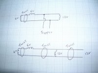
Quick scribble..
Then it depends if they are elevated or Gnd referenced ..
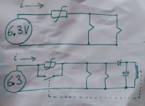
You can put a timed current limit thermistor in line with a relay contact that shorts out the thermistor after a set time..the thermistor goes in series with heater supply or a current limit as suggested..
Regards
M. Gregg
Attachments
Last edited:
Here is a pic from here in the past..
I have used something similar in the past with simple transistor timing..you could even latch the relay with thyristor and trigger the gate and latch the relay, reset at power off.
NB I don't know where you are getting the DC from but if its a DC supply and the current with cold heaters is to high the supply will go into current limit or thermal shut down and it will just sit there with no working heaters the cold resistance of heaters is much lower than hot heaters. That's when you need a slow (soft start).
Once the heaters are warm the current is reduced and the supply will probably work OK..but its misleading and when they cool down the supply will fail again.
Regards
M. Gregg
Attachments
Last edited:
ahh thanks man, i will consider that sometime, for now getting my tube amp to work. all the tubes light up accordingly and my wiring should be good but i am getting no signal. on the output tube, the anode is connected to the 5k primary and b+ is connected to the other primary input. what am i doing wrong? at first i thought it was the speaker and it was in fact the wrong way but still no joy. should i be wiring my OPT different? thanks.
p.s i know how amps work - push pull, not very familiar with SE output stages
p.s i know how amps work - push pull, not very familiar with SE output stages
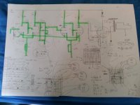
well it is sort of a combo - im using my own knowledge to make the 2 preamp stages and then having a single ended output tube on the other, all ran by 12v (don't worry, the output tube is a space charge tube) let me find a schematic to compare.
Aran
EDIT - it is based off the space charger PP (also on this forum) but instead of PP config. i chose SE but like i said, am having alot of trouble with and actual output stage (i have built it all to a schematic, not the PP output like i mentioned but it simply does not output anything and now the output tube's heater doesn't glow, great!)
Last edited:
yeah, Nigel that's what i figured - if i can run the two tubes in series with the mains, it would work but i forgot that i had jumpered the first tube heater to ground for 6v testing, and so it overvolted as it had a direct route to ground, now I'm trying to wrap my head around the OPT wiring and why it does not work based off the schematics
Aran
Aran
Aran,yeah, Nigel that's what i figured - if i can run the two tubes in series with the mains, it would work but i forgot that i had jumpered the first tube heater to ground for 6v testing, and so it overvolted as it had a direct route to ground, now I'm trying to wrap my head around the OPT wiring and why it does not work based off the schematics
Aran
The mains dropper was an old and dangerous idea.
Never try to run any part of a circuit direct from the mains.
The reason is the fault and shock current is not limited and contact even by accident can and often is fatal.
So you should run the heaters from a dedicated supply ie even 12V DC is OK from a supply that can handle the running current.
However the start up current (cold start) can be an issue more with DC supplies and regulators.
So dedicated mains isolation transformers are the thing to use. You can use separate transformers for HT (B+) and heaters and even feed each supply with its own transformer. One for the B+ and one for the heaters and one for the bias supply if you need one.
The other thing is the way heaters are used sometimes means you have to elevate the heater supply eg on SRPP the top tube in the chain needs to be higher reference than the lower tube.
So sometimes you can float the heater chain, sometimes its ground referenced, and sometimes the 6.3 or 12V is lifted with another voltage to keep it above ground. This means that a heater supply is 6.3 or 12V between heaters but can be 100V above ground. So don't just assume that heater voltage is safe if you expect 12V or 6.3.
Another issue with mains droppers was if the heater chain went open circuit the ends of the chain were now at mains potential and that is why old Xmas tree lights were so dangerous. When a lamp failed it put the two wires at Live and neutral potential people thought it was safe because 12V lamps were used ie 20 X 12V = 240V in series each lamp gets 12V until one goes open circuit then the whole chain is at 240V. So people then changed and substituted a lamp unscrewing each in turn and screwing a new lamp in. They did not know they were holding live 240V mains in their hands even children were asked to try a new lamp.
Get the 12V supply working
Now if we can have a circuit diagram of what you are doing we can fault find..
even a pen and paper one is OK.Regards
M. Gregg
Last edited:
- Status
- This old topic is closed. If you want to reopen this topic, contact a moderator using the "Report Post" button.
- Home
- Amplifiers
- Tubes / Valves
- wiring tubes in series