It would probably be self evident if I knew what I was doing, but I'm not sure exactly how to wire my transformers to the Tubelab SE. I'm using type 45 tubes and an Edcor XPWR-131 transformer.
This thread here: http://www.diyaudio.com/forums/tubes-valves/126672-tubelab-wiring.html explains how to wire a Hammond transformer up, but the wire colors are all different.
Here's the pinout for the XPWR-131: http://www.knizefamily.net/russ/blog/wp-content/uploads/2009/03/edcor-xpwr131.jpg
Any help would be appreciated. Sorry if this is a stupid question.
The yellow wires are the 5V rectifier heater winding (TI-2 and TI-3). Same as Hammond.
The brown wires are the 6.3VCT winding (TI-7 and TI-8). The white/brown is the center tap (TI-6). Hammond uses green.
The HT winding colors are a little goofy. The white wire is the HT CT, which goes to TI-1. Hammond is red/yellow. Which pair you pick for TI-4 and TI-5 depend on if you are using 45s or 300Bs. For 45s, use the black/red and white/orange pair. For 300Bs, use the red and orange pair. Doesn't matter which one goes on which terminal.
I checked the sticker it came with, and the colors do indeed match up.
If it wouldn't try everbody's patience too much, can I confirm how I should hook up the CXSE25-8-5k OPTs? Does the B+ need to be connected, or do I just need to connect the plate and screen? The common output from both OPTs should be run to the ground cable on the power cable as well, correct?
If it wouldn't try everbody's patience too much, can I confirm how I should hook up the CXSE25-8-5k OPTs? Does the B+ need to be connected, or do I just need to connect the plate and screen? The common output from both OPTs should be run to the ground cable on the power cable as well, correct?
Last edited:
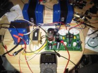
I wired the transformers up last night, and to my great surprise it actually seems to be working! I fully expected it to leap up and murder me when I plugged it in, but I was able to check B+, B- and the filament voltages and everything looks okay so far. I only had one pair of mini grabbers, though, so I stopped after adding the rectifier. I'm going to pick up another pair today and continue check out. Thanks for the help!
Attachments
If my math is right, at 2x300 mA filament current, the 2.2 ohm resistor will dissipate almost 800 mW. It should be at least a 2 W type, though, a 3 W or 5 W would be preferred. Is it possible that you used a 0.5 W or 0.25 W type? That would cause the resistor to get rather cranky and emit smoke after a bit.
~Tom
~Tom
I checked, it's 2.2ohms even after it cooked itself. With both 5842s in, neither tube lights up and R3 starts to smoke after less than a minute. With just one in, the tube lights up and R3 starts to stink like it's burning, but it doesn't seem to want to smoke itself.
The 5842s I bought are Russian, I wonder if they aren't really 5842's. They say CC45P E 0280
The 5842s I bought are Russian, I wonder if they aren't really 5842's. They say CC45P E 0280
Sure that's not 6C45P? If so, the heater current requirements are higher. 440mA each, IIRC. Some eBay vendors peddle these as 5842/417A, but they are not quite the same. You would need 1.5 ohm, 3W or 5W here to get the same drop. If you bought spares when you got the parts, put two of the 2.2 ohm resistors in parallel to get nearly the same effect.
According to their web site, radio shack does carry a 1 ohm 10w wire wound resistor (I already have one) and a .47ohm 5w wire wound resistor. If I put them in serial, would that work as a temporary work around? Is inductance going to be an issue?
Or would it be better to buy six 1/2 watt resistors of the appropriate values to add up to 1.5 ohms and wire them up in parallel or serial?
Or would it be better to buy six 1/2 watt resistors of the appropriate values to add up to 1.5 ohms and wire them up in parallel or serial?
On closer inspection, you're exactly right. It says 6c45P. I'll check my spare parts bag to see if I got an extra one.
I saw this post at work today, but couldn't look this stuff from work (big brother is watching comuter use). The 6C45P has a completly different pinout than the 5842, and will not work in the Tubelab SE board. The 5842 has the filament on pins 3 and 9. Pins 3 and 9 are both connected to the cathode in the 6C45P, so they are shorted together. This will make R3 very unhappy as you found out, and may damage other parts too, since none of the pins match a 5842.
I'm guessing that you got these "5842 equivalents" from the same Ebay seller that sells some "6AQ5 equivalents" that have 9 pins on them. A 6AQ5 only has 7 pins. Maybe the word "equivalent" lost something in translation.
The purpose of R3 was questioned in a previous post. In my board with the typical Hammond 7 volt filament windings I was getting over 7 volts on the 5842 heater. 2.2 ohms gets me to 6.3 volts even with silicon diodes. That value seems to work in most boards except maybe a 2A3 board. Most experts will agree that tube life is compromized by high filament voltage, and slightly low voltage is preferred over too much voltage. If your 5842 is running below 6 volts a lower resistor value may be worth trying.
- Status
- This old topic is closed. If you want to reopen this topic, contact a moderator using the "Report Post" button.
- Home
- More Vendors...
- Tubelab
- Wiring the transformer to the Tubelab SE