wintermute said:
Did you use generic brand components in yours Mick, or more esoteric ones? Mines a bit of a mix, but nothing outrageous.
Tony.
I did not take particular care in getting fancy parts. The polyester caps are Wima and the electrolytics Roederstein. I bought the resistors at a local shop and I dont think that they are something special.
Actually, as a physicist I find it very hard to believe that exotic resistors are better (whatever that means) than normal ones. As long as you dont use wirewounds, a resistor is a resistor and ohmic resistance is its dominating property. This might be different with capacitors, which from a physicists standpoint are a much more complex issue.
Mick
I know what you mean Mick, I get very skeptical about things unless I can see something that could possibly make a difference. I used 7c metal film resistors in mine, but for the decoupling caps and feedback caps I used nichicon FG, which are a little more expensive but not by a lot. The PS caps I used panasonic FC's because of their low ESR (and also the generaly good rap people have given them), and the decoupling cap bypasses I used WIMA polyesters (I really didn't think that polypropylene would make a difference here, and the polyesters are so much smaller).
I had been pretty sceptical about caps too (except for low ESR because I could see that could help in lowering the output impedance of the PS) but I read Walt Jungs choosing capacitors article, and well lets just say it has me thinking there is more to the claims that caps can make a big difference than one might first think. I used a polyproylene (nothing exotic) for the output compensation cap, because itis effectively in the signal path.
I thought about getting some Welwyn RC55 resistors for the feedback resistors, but mainly because they are highly accurate 0.1% tolerance, and highly stable with temp changes (which could be important when mounted so close to the chip). but I ended up using the 7c ones")
Tony.
I had been pretty sceptical about caps too (except for low ESR because I could see that could help in lowering the output impedance of the PS) but I read Walt Jungs choosing capacitors article, and well lets just say it has me thinking there is more to the claims that caps can make a big difference than one might first think. I used a polyproylene (nothing exotic) for the output compensation cap, because itis effectively in the signal path.
I thought about getting some Welwyn RC55 resistors for the feedback resistors, but mainly because they are highly accurate 0.1% tolerance, and highly stable with temp changes (which could be important when mounted so close to the chip). but I ended up using the 7c ones
Tony.
OK,
after a weekend of doing nothing at all, I have today almost finished the chassis, and in the process knocked the amp of the overly cluttered desk and broken the ps board
Oh well the project seemed to be going to well to be true no project is complete without at least one disaster!
No major problem, will try to glue with some superglue, and resoder the broken tracks, even if I can't mend it, should not affect operation, unless I decide to add more caps.
The other channel is complete except for power supply, input and output connections so should get it done tomorrow hopefully. fingers crossed.
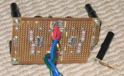
well I said I was going to post a pic of the ps board so here it is
Tony.
note that the top track on the left has some cuts in it because I was using it for practice, before I did the real ones
after a weekend of doing nothing at all, I have today almost finished the chassis, and in the process knocked the amp of the overly cluttered desk and broken the ps board
Oh well the project seemed to be going to well to be true
no project is complete without at least one disaster!No major problem, will try to glue with some superglue, and resoder the broken tracks, even if I can't mend it, should not affect operation, unless I decide to add more caps.
The other channel is complete except for power supply, input and output connections so should get it done tomorrow hopefully. fingers crossed.
well I said I was going to post a pic of the ps board so here it is
Tony.
note that the top track on the left has some cuts in it because I was using it for practice, before I did the real ones
Attachments
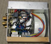
Well I have fixed the ps board, still haven't wired up the remaining channel, but I have finished the chassis
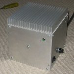
It is really rough, but considering that it is my first attempt at fabricating a chassis, I did it in a hurry, and I only had a battery operated drill and jigsaw to work with I think it turned out ok
Kinda an industrial look.
Tony.
It is really rough, but considering that it is my first attempt at fabricating a chassis, I did it in a hurry, and I only had a battery operated drill and jigsaw to work with I think it turned out ok
Kinda an industrial look.
Tony.
Attachments
Thanks Karma,
truth be known it is strictly my second I wasn't counting the first as it is mostly wood, but I guess I should have. It can be seen here in the ugly looking amp thread
It may compete well with your first effort
Tony.
truth be known it is strictly my second
I wasn't counting the first as it is mostly wood, but I guess I should have. It can be seen here in the ugly looking amp thread It may compete well with your first effort
Tony.

In this Vikash you are 100% correct I ran out of patience!! I put the tungsten carbide cutting bit in the dremel, cranked it up to 37,000 RPM and went for it..... not the right approach, even with a template!! just cut the template too
My dad has a dremel scroll saw, and a table saw, only problem is he is 7 hours drive away.......
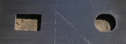
and just to show upupa that I have improved here is a pic of the other two holes, yeah I know it still looks like I used a round file on the rectangular hole (I didn't I swear) I just went too close with the drill on on the first hole the oval hole for the fuse is the final one. As you can see I'm getting better (though still not perfect).... at least with these ones you can't see into the case around them when the switch and fuse are installed
Tony.
I ran out of patience!! I put the tungsten carbide cutting bit in the dremel, cranked it up to 37,000 RPM and went for it..... not the right approach, even with a template!! just cut the template too My dad has a dremel scroll saw, and a table saw, only problem is he is 7 hours drive away.......
and just to show upupa that I have improved here is a pic of the other two holes, yeah I know it still looks like I used a round file on the rectangular hole (I didn't I swear) I just went too close with the drill on on the first hole
the oval hole for the fuse is the final one. As you can see I'm getting better (though still not perfect).... at least with these ones you can't see into the case around them when the switch and fuse are installed Tony.
Attachments
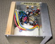
It's done..... well almost
I've now almost completely finished my gainclone, the only thing remaining is to screw the terminal block to the base (oh and perhaps connect the 0V to the case) chassis is earthed to the mains, but ps isn't.... need to make an earth buster first though, as I need it for use with my pc). hmmmm I wonder where I can fit an earth buster
Tested the second channel and it measured 1.2mV dc offset with input shorted, which compares nicely with the 1.4mV of the other channel.
Haven't done a listening test yet as it is too late, will do one tomorrow, along with an RMAA test.
It's been a lot more work than I thought it would be, but has been fun I'm going to do a proper writeup of the whole process in gory detail but it might be a while before I get it up on the web
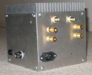
I think for my next chassis I will go with something a little more conventional, this one was made to match the heatsink I had, and as you can see from the photo below it is pretty tight. Hopefully it will not have a hum problem due to the compactness, but the test of the first channel was promising.
Tony.
I've now almost completely finished my gainclone, the only thing remaining is to screw the terminal block to the base
(oh and perhaps connect the 0V to the case) chassis is earthed to the mains, but ps isn't.... need to make an earth buster first though, as I need it for use with my pc). hmmmm I wonder where I can fit an earth buster Tested the second channel and it measured 1.2mV dc offset with input shorted, which compares nicely with the 1.4mV of the other channel.
Haven't done a listening test yet as it is too late, will do one tomorrow, along with an RMAA test.
It's been a lot more work than I thought it would be, but has been fun
I'm going to do a proper writeup of the whole process in gory detail but it might be a while before I get it up on the web I think for my next chassis I will go with something a little more conventional, this one was made to match the heatsink I had, and as you can see from the photo below it is pretty tight. Hopefully it will not have a hum problem due to the compactness, but the test of the first channel was promising.
Tony.
Attachments
some objective tests.
OK so I have run some objective tests.
1. 1000uF per rail per channel results in some pretty serious sag in the ps when pushed hard. Voltage drops from about 27.5V to 23.5V tried with various freqs from 20Hz to 4000Hz. all behaved about the same with regards to voltage drop.
2. ripple in the PS is quite high. no load it is about 130mv when pushed to just before clipping (into an 8 ohm load both channels) it increases to about 1.8V. With say a 1Khz sine wave the ripple is nice looking (even if big) at full power. with a 20 Hz sine wave at full power the ripple is very scary looking!!!! more capacitance would no doubt help here.... whether I decide to add any not sure, I'll wait and see how it sounds
3. Clipping performance is well pretty ordinary really (had read this before, wanted to confirm for myself. picture attached, note the bottom channel is the output sine wave off the dummy load. ideally it should still look like a sine wave with flat tops and bottoms, as you can see once the amp starts clipping the waveform gets rather distorted. This was a 1Khz sine wave. top channel was ripple, I set the preamp to 0.1X so the ~300mv it is probably in fact 3V!!!! the transformer is a 300VA BTW.
4. I've done the RMAA test can be seen here ----> http://home.exetel.com.au/wintermute/rmaa/gc4.htmhttp://home.swiftdsl.com.au/~tonywww/rmaa/gc4.htm Not stella but not bad either I use a sound card preamp in between the amp and the sc. set to 0.1X the amp didn't have quite enough grunt to get into the yellow zone, set to 1X I couldn't get any decent results at all. so I bumped the gain up slightly on my SC to get into the ok zone for RMAA when running in 0.1X mode. Test of just the sound card preamp can be found here ----> http://home.exetel.com.au/wintermute/rmaa/sc_preamp_14_new_battery.htmhttp://home.swiftdsl.com.au/~tonywww/rmaa/sc_preamp_14_new_battery.htm
Note that I suspect some anomalies with the crosstalk results are due to my test leads...
5. I do need some thermal grease on the chips!! at least for very high output. the heat sink got quite warm (maybe 35 deg C), and the chips themselves too hot to touch (not blister inducing but hot). I was pusing it quite hard though
That's all for now
Tony.
OK so I have run some objective tests.
1. 1000uF per rail per channel results in some pretty serious sag in the ps when pushed hard. Voltage drops from about 27.5V to 23.5V tried with various freqs from 20Hz to 4000Hz. all behaved about the same with regards to voltage drop.
2. ripple in the PS is quite high. no load it is about 130mv when pushed to just before clipping (into an 8 ohm load both channels) it increases to about 1.8V. With say a 1Khz sine wave the ripple is nice looking (even if big) at full power. with a 20 Hz sine wave at full power the ripple is very scary looking!!!! more capacitance would no doubt help here.... whether I decide to add any not sure, I'll wait and see how it sounds
3. Clipping performance is well pretty ordinary really (had read this before, wanted to confirm for myself. picture attached, note the bottom channel is the output sine wave off the dummy load. ideally it should still look like a sine wave with flat tops and bottoms, as you can see once the amp starts clipping the waveform gets rather distorted. This was a 1Khz sine wave. top channel was ripple, I set the preamp to 0.1X so the ~300mv it is probably in fact 3V!!!! the transformer is a 300VA BTW.
4. I've done the RMAA test can be seen here ----> http://home.exetel.com.au/wintermute/rmaa/gc4.htmhttp://home.swiftdsl.com.au/~tonywww/rmaa/gc4.htm Not stella but not bad either
I use a sound card preamp in between the amp and the sc. set to 0.1X the amp didn't have quite enough grunt to get into the yellow zone, set to 1X I couldn't get any decent results at all. so I bumped the gain up slightly on my SC to get into the ok zone for RMAA when running in 0.1X mode. Test of just the sound card preamp can be found here ----> http://home.exetel.com.au/wintermute/rmaa/sc_preamp_14_new_battery.htmhttp://home.swiftdsl.com.au/~tonywww/rmaa/sc_preamp_14_new_battery.htmNote that I suspect some anomalies with the crosstalk results are due to my test leads...
5. I do need some thermal grease on the chips!! at least for very high output. the heat sink got quite warm (maybe 35 deg C), and the chips themselves too hot to touch (not blister inducing but hot). I was pusing it quite hard though
That's all for now
Tony.
Attachments
Last edited:
Hi Javven,
hehehe no need to worry about me thinking you are trolling my initial test of one channel playing music at a bit higher than normal level for 30 minutes resulted in no increase in temp on the heatsink, and a barely warm chip I wasn't sure if I was going to be pulling it apart again, so decided not to put the HSC in at that stage (it's messy stuff), and at that stage it didn't really seem necessary.
This latest pretty much worst case test shows that it would be a good idea afterall
I have a tube of unick so I think I will put some on to be on the safe side
Just did some power tests and the results were interesting adjusted level on my pc until just before clipping.
20 Hz only managed 13.2 V so about 21W 10Khz managed 20.5V so about 52W! (into 8 Ohm dummy load, rail voltage about +-27.5V) no wonder people complain about lack of bass with low capacitance supplies!
Tony.
edit: note about ripple with 20Hz sine wave being scary, the level was too high and the sc preamp was clipping not so bad afterall...
pic attached. top trace is the ripple, about 2.4V and the bottom one is the output off the dummy load.
hehehe no need to worry about me thinking you are trolling
my initial test of one channel playing music at a bit higher than normal level for 30 minutes resulted in no increase in temp on the heatsink, and a barely warm chip I wasn't sure if I was going to be pulling it apart again, so decided not to put the HSC in at that stage (it's messy stuff), and at that stage it didn't really seem necessary.This latest pretty much worst case test shows that it would be a good idea afterall
I have a tube of unick so I think I will put some on to be on the safe side
Just did some power tests and the results were interesting
adjusted level on my pc until just before clipping. 20 Hz only managed 13.2 V so about 21W 10Khz managed 20.5V so about 52W! (into 8 Ohm dummy load, rail voltage about +-27.5V) no wonder people complain about lack of bass with low capacitance supplies!
Tony.
edit: note about ripple with 20Hz sine wave being scary, the level was too high and the sc preamp was clipping
not so bad afterall... pic attached. top trace is the ripple, about 2.4V and the bottom one is the output off the dummy load.
Attachments
Errata!
It seems my multimeter gets quite inaccurate at higher ac freqs.... seems to be still ok at 5Khz but at 10Khz is extermely inaccurate....
just checked with true RTA and whilst the meter is reading 20.9V at 10Khz, True RTA is reading 14.4V I suspect that the 14.4V is actually more like it
so feel free to ignore my previous comments about the bass being effected
Tony.
pull up a chair
Hi Carlos,
You may want to sit down It could be a while!!! I'm not really set up to do A/B comparisons.....
I finished the amp this afternoon. I found that without the 0V connected to the chassis it had some hum and buzzzzz I was concerned about earth loops with my PC so I made an earth loop buster based on the design here -----> http://sound.westhost.com/earthing.htm Seems I'm posting this link a lot lately
Result I hear you ask??? Absolutely dead quiet!!!!! I'm so happy because my other amp has always been very noisy! I probably should clarify that you can only here the buzz in it if you are close to the speakers probably within 20 cm or so.
(The ironic thing is the noisy amp gets a better S/N ratio in RMAA than this one) though I did do the rmaa test without the earth loop buster so will have to retest.
Good news Vikash I think my grounding system was a complete success!!!! I'm particularly impressed with the quietness when you consider how tightly packed it all is!
To give an idea how quiet this amp is, with no input connected (not even shorted) and this amp doesn't have a volume pot so max volume, I have to put my ear physically against the speaker to hear anything. The tweeter has the slightest hiss and the mid a tiny amount of hum, the woofer I'm not sure whether I could hear any hum or not. With the tweeter if I moved even 2cm away I couldn't hear anything, same with the mid.
Ok so how does it sound??? Well I haven't listened to any music on it yet; I plugged it into my TV (lowe xelos) and used the volume control of the TV.... too much hassle to drag the pc downstairs or the speakers upstairs. My first impression was that the treble was more pronounced than my normal amp. sillibance was more noticeable (though I hadn't listened to the former for a day or two). Flicked channels listening to different peoples voices (always a good test I think) and nothing glaring or nasty, sounded nice. Kept thinking the treble was more pronounced, wondered if that was simply because I had read that about others impressions and my brain was making it so
After a while I decided it was time to pack up, reinstalled the usual amp and had a listen.... silibance was still there, maybe not quite as pronounced.... was undecided. Since then I have looked at the rmaa results for my old amp, it starts rolling off (very slowly) at about 5Khz and is down about .4db at 20Khz. The GC is pretty much flat out to 20Khz before it starts to roll off. Now I'm pretty skeptical as to whether I can actually hear what may amount to maybe .2db difference at say 10Khz...... maybe I can who knows!!
If there are any big differences with the GC and my existing 100W mosfet (apart from power handling, and clipping performance, the GC is only managing about 20W with the current PS, and the mosfet will happily deliver 110W into the same load) then I suspect I'm not going to be able to hear it very well until I finish my morel MTM's.
If I feel up to the challenge I may cart the pc downstairs, gut the series 200 so I can splice into the power amp direct and do some listening comparisons (still not true A/B but close).... but in reality this amp was supposed to be built to allow me to test loudspeakers (and active crossovers) so I think maybe I should get on with the loudspeaker side and not get too bogged down in amp comparisons
Maybe my series 200 is better than I thought (yeah I know I only listened to TV ) maybe when I listen to music I will hear the difference, but at this stage (at least with my current speakers) I suspect not.......
Oh and another pic not much different to before, but it is finished . Now has earthloop buster installed, and terminal block screwed down, oh and heat sink compound on the chips, not that you can see it!
I connected one side of the earth loop buster to the same point that the mains earth is connected to the chassis, and the other side to the point where the 0V line connects to the terminal block, where the transformer wires terminate. Decided this was the best place for saftey in case of a transformer meltdown, and certainly seems agreeable from a noise perspective
Tony.
Hi Carlos,
You may want to sit down
It could be a while!!! I'm not really set up to do A/B comparisons..... I finished the amp this afternoon. I found that without the 0V connected to the chassis it had some hum and buzzzzz I was concerned about earth loops with my PC so I made an earth loop buster based on the design here -----> http://sound.westhost.com/earthing.htm Seems I'm posting this link a lot lately
Result I hear you ask??? Absolutely dead quiet!!!!! I'm so happy because my other amp has always been very noisy! I probably should clarify that you can only here the buzz in it if you are close to the speakers probably within 20 cm or so.
(The ironic thing is the noisy amp gets a better S/N ratio in RMAA than this one) though I did do the rmaa test without the earth loop buster so will have to retest.
Good news Vikash I think my grounding system was a complete success!!!! I'm particularly impressed with the quietness when you consider how tightly packed it all is!
To give an idea how quiet this amp is, with no input connected (not even shorted) and this amp doesn't have a volume pot so max volume, I have to put my ear physically against the speaker to hear anything. The tweeter has the slightest hiss and the mid a tiny amount of hum, the woofer I'm not sure whether I could hear any hum or not. With the tweeter if I moved even 2cm away I couldn't hear anything, same with the mid.
Ok so how does it sound??? Well I haven't listened to any music on it yet; I plugged it into my TV (lowe xelos) and used the volume control of the TV.... too much hassle to drag the pc downstairs or the speakers upstairs. My first impression was that the treble was more pronounced than my normal amp. sillibance was more noticeable (though I hadn't listened to the former for a day or two). Flicked channels listening to different peoples voices (always a good test I think) and nothing glaring or nasty, sounded nice. Kept thinking the treble was more pronounced, wondered if that was simply because I had read that about others impressions and my brain was making it so
After a while I decided it was time to pack up, reinstalled the usual amp and had a listen.... silibance was still there, maybe not quite as pronounced.... was undecided. Since then I have looked at the rmaa results for my old amp, it starts rolling off (very slowly) at about 5Khz and is down about .4db at 20Khz. The GC is pretty much flat out to 20Khz before it starts to roll off. Now I'm pretty skeptical as to whether I can actually hear what may amount to maybe .2db difference at say 10Khz...... maybe I can who knows!!
If there are any big differences with the GC and my existing 100W mosfet (apart from power handling, and clipping performance, the GC is only managing about 20W with the current PS, and the mosfet will happily deliver 110W into the same load) then I suspect I'm not going to be able to hear it very well until I finish my morel MTM's.
If I feel up to the challenge I may cart the pc downstairs, gut the series 200 so I can splice into the power amp direct and do some listening comparisons (still not true A/B but close).... but in reality this amp was supposed to be built to allow me to test loudspeakers (and active crossovers) so I think maybe I should get on with the loudspeaker side and not get too bogged down in amp comparisons
Maybe my series 200 is better than I thought (yeah I know I only listened to TV
) maybe when I listen to music I will hear the difference, but at this stage (at least with my current speakers) I suspect not.......Oh and another pic not much different to before, but it is finished
. Now has earthloop buster installed, and terminal block screwed down, oh and heat sink compound on the chips, not that you can see it!I connected one side of the earth loop buster to the same point that the mains earth is connected to the chassis, and the other side to the point where the 0V line connects to the terminal block, where the transformer wires terminate. Decided this was the best place for saftey in case of a transformer meltdown, and certainly seems agreeable from a noise perspective
Tony.
Attachments
OK Well I know it has been almost 4 years since the previous post, but I felt that since I recently actually did use the gainclone to listen to some music I probably should at least report something
Yes it has sat in the cupboard for those four years. Not because it isn't any good, but because I built it for testing speakers, and I haven't done anything on my speakers for that long!! I have no preamp so I can't use it in place of my main amp (practically).
Well my mosfet amp had a little problem a couple of weeks ago, My Daughter decided to shove a chopstick in the hole where the balance pot used to be, and broke a lead off a cap, so while I found the time to fix that I put the gainclone into service hooked up to the HTPC.
I played a number of CD's and it sounded very nice indeed. But my original comments about needing to finish my speakers before I can really critically do a listening test still stand. The amp definitely seems to have more treble than my series 200 mosfet, but I think that is a problem with the preamp section of the series 200. I actually had to adjust the lpads on the speakers to compensate for the extra ssss ing.
The thing that surprised me the most was the quality of the bass. I was expecting it to be lacking in this respect with only 1000uf per rail per channel in the power supply, but it seems fine to me.
For the limited time I used it, I now think that once I finish my MTM's and do a preamp and active crossover, I will be quite happy to use this little amp to drive the MTM's and use the mosfet for the stereo subs.... at some point I might want to do another discrete amp, but I think this one (once I get the rest of the projects done) will keep me happy for quite some time
The bang for buck on this amp is truly sensational!!
Tony.
- Status
- This old topic is closed. If you want to reopen this topic, contact a moderator using the "Report Post" button.
- Home
- Amplifiers
- Chip Amps
- Wintermute's Gainclone