Yagoolar, I think the plate limit on 6С4П is 160V and you'll probably need a B+ of 300V or more to get the voltage swing you need, so I'd stick with 6С45П (max. V = 250V IIRC) if you want to stay all-triode. (Plus, 6С45П's seem to average higher µ's).
Anyway, please let us know what you end up doing and how it turns out.
Good luck.
Max. anode voltage for 6C45 is 150V.
That is an interesting idea about using the 7903. How would that be wired in? Having that infront of the driver tube would allow a lot more tubes to be swapped in.
I'm using it in 1:8 although you can do 1:4. All depends on the mu of the triode you're looking to use. My implementation is a bit crazy: 7903 + 46 in filament bias. It provides 200Vpp at less than 0.2% which works nicely in my 4-65a output stage.
I've got a photocopy of a (Russian) datasheet from when I was building a spud amp years ago that translates "Max. continuous DC = 150V" – (i.e. that's its maximum quiescent V or operating point). "Max peak = 250V"Max. anode voltage for 6C45 is 150V.
Don't remember where I got it from; the only one I can find online currently is the one from Mashpriborintorg (for the 6С45П-Е) that Frank Philipse hosts.
Don't know if there's a difference, but if so, my bad.
"Max peak = 250V"
Take this with a large grain of salt, but I've run the 6C45-pe at 190 vpk for years with no failures.
I don't want to hi-jack this thread but wanted to say thanks to everyone. I went home last night and dragged out my GM70 project and listed out everything I have to do to complete it.
all you miss to be on topic is ... winter

I don't want to hi-jack this thread but wanted to say thanks to everyone. I went home last night and dragged out my GM70 project and listed out everything I have to do to complete it.
+1
I've got a bunch of GM70 and 813s but after my 4-65a SE 100% DHT madness I had enough for a while. Certainly I will try 814 as output but will be sometime until I come back to the GM70s...
Miller Capacitance is about Cgp*(Av+1) or approximately Cgp*(mu+1) depending on the gain of your driver. Just to illustrate impact lets look at the D3a which has mu of 80 and Cgp of about 10pf (if my memory works well) in triode mode. Therefore your equivalent Ci or Cmiller (without adding Cgk) is 810pF! You will need a good line stage driver with an output impedance below 10k at least to avoid suffering some treble loss.
Ale
Ale
I started thinking about what you had written about Miller capacitance. Datasheets I have read present Cag capacitance for "true" pentode mode. How can I calculate or find triode strapped capacitance values for, say, E180F?
E180F Philips data gives direct anode-grid1 capacitance as 0,1pF (can ignore this). Also gives various figures for Cg1 to g3/g2/K/heater at 6,6 to 11pF depending on test condition. The Miller-influenced portion of this is probably a little under a half.
you could try to improve the accuracy of the actual value (including Miller effect) by testing with a signal generator.
wire the E180F as triode, with gain of 10, or whatever gain required for your design. Using a large grid resistor (connect as a stopper) of 220K to 680K, and apply a signal generator to the grid.
Sweep frequency upward until the -3dB frequency [f3] is measured at the anode.
Find the effective input capacitance:
f3 = 1/(2П*Rgrid*Cinput)
Example: for 470K and effective input capacitance of 20pF, you should see a f3 at 16931.4 Hz.
Should be able to test with a Sound card and read the f3 directly, with good audio test software.
Last edited:
I will measure Cm for the acomplished E180F - 6C4C PF amplifier and post my findings in my another thread and put a link here (http://www.diyaudio.com/forums/tubes-valves/175429-yagoolars-tube-amp-projects-8.html#post3334933).
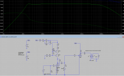
I agree with both of you. I just attached the copy of the schematic I had drawn in 2004 - see the date in the left bootom corner. The same year I joined diyaudio.com community. Since then I learnt a lot. Anywsy, thanks for your comments.
PS. Actually - three of you.
As to primary inductance of PF transformer - I lost the email with specs from the manufacturer. I have measure it. Ro = 6 ohm, Ra=7kohm
It measures:
Lpri=10.7 H
Lsec=9.2 mH
Rpri= 51 R
Rsec=0.2 R
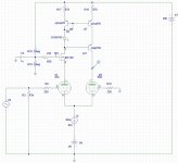
Perhaps a GG?
Hi,
I have used something like this to drive my GM70 SE. I now run a similar setup but with 6n6p, no sand and a 1:4 input transformer. Both works very well
It sort of takes the Miller capacitanse out of the eqation
BR,
Anders
Hi,
I have used something like this to drive my GM70 SE. I now run a similar setup but with 6n6p, no sand and a 1:4 input transformer. Both works very well
It sort of takes the Miller capacitanse out of the eqation
BR,
Anders
Attachments
Last edited:
- Status
- This old topic is closed. If you want to reopen this topic, contact a moderator using the "Report Post" button.
- Home
- Amplifiers
- Tubes / Valves
- Winter is coming... Time to start GM70 SE parafeed amp