There are a lot of factors that influence thermal stability, one being the impedance of the drive or biasing circuitry. Icbo doubles with each 6*C of junction temperature and that current can cause forward biasing of the transistor and lead to thermal runaway even in Class B.
Ok. So... my reading suggested that thermal runaway was something along the lines of: A fixed bias accross a BE junction causes current to flow. As the temperature rises, the amount of current that is allowed to flow increases which causes more heat...
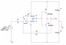
w/rt to distortion, here's a spice sim of a class B in a feedback amplifier and a fft of the output, what is it that spice doesn't know about?
w/rt to distortion, here's a spice sim of a class B in a feedback amplifier and a fft of the output, what is it that spice doesn't know about?
Attachments
I'm really surprised some people will find something to argue
about even with the the most basic concepts of electronics.
I wish they would read a decent textbook and stop
telling people what they think a concept really is.
Thermal runaway is caused by instability of DC biasing of a
transistor, whatever prompts the instability is not relevant,
destruction must be due to a runaway increase in DC bias
current because of thermal instability to classed be as
thermal runaway.
Class C by definition cannot suffer thermal runaway as it no DC bias.
Class C also by definition exhibits crossover distortion that cannot be
removed by any real world application of negsative feedback.
With standard single pole compensation feedback falls at 6dB/octave,
consequently the crossover distortion rises with frequency.
Not only that : At ~1k crossover distortion components are
liberally produced right up to 20K and beyond. Standard 1 pole
compensation above the turnover frequency spectrally skews
these components increasing higher harmonics at 6dB/octave.
(lees effectively reducing the harmonics at 6dB/octave)
") sreten.
sreten.
about even with the the most basic concepts of electronics.
I wish they would read a decent textbook and stop
telling people what they think a concept really is.
Thermal runaway is caused by instability of DC biasing of a
transistor, whatever prompts the instability is not relevant,
destruction must be due to a runaway increase in DC bias
current because of thermal instability to classed be as
thermal runaway.
Class C by definition cannot suffer thermal runaway as it no DC bias.
Class C also by definition exhibits crossover distortion that cannot be
removed by any real world application of negsative feedback.
With standard single pole compensation feedback falls at 6dB/octave,
consequently the crossover distortion rises with frequency.
Not only that : At ~1k crossover distortion components are
liberally produced right up to 20K and beyond. Standard 1 pole
compensation above the turnover frequency spectrally skews
these components increasing higher harmonics at 6dB/octave.
(lees effectively reducing the harmonics at 6dB/octave)
sreten.I'd like to cast a vote too! A true class B amp, where the drivers and outputs are "off", will NOT runaway thermally.
A true class B amp sounds like dookie compared to one that is moderately biased, even with gobs of feedback. It would not be a hi-fi amplifier, that's for sure. In a TV or clock radio, you probably wouldn't notice it enough to care.
A true class B amp sounds like dookie compared to one that is moderately biased, even with gobs of feedback. It would not be a hi-fi amplifier, that's for sure. In a TV or clock radio, you probably wouldn't notice it enough to care.
azira said:w/rt to distortion, here's a spice sim of a class B in a feedback amplifier and a fft of the output, what is it that spice doesn't know about?
Not sure about real components but if you go through reasoning, you will see that feedback will take out cross-over distortion. It is, however, arguable (or unlikely depending on your perspective) that the same is true with real life circuits or simulations using reasonably good models.
a much interesting plot would be to chart Vin, Vo and Pin 6 of the Opamp. You will see that the voltage on Pin6 crosses zero very fast (to reduce cross-over distortion at Vo).
sreten said:Thermal runaway is caused by instability of DC biasing of a
transistor,
i have always thought that thermal run-away is caused by hot spotting which may or may no thave anything to do with biasing.
sreten said:I'm really surprised some people will find something to argue
about even with the the most basic concepts of electronics.
I wish they would read a decent textbook and stop
telling people what they think a concept really is.
Thermal runaway is caused by instability of DC biasing of a
transistor, whatever prompts the instability is not relevant,
destruction must be due to a runaway increase in DC bias
current because of thermal instability to classed be as
thermal runaway.
1) Is 0-volts at the base considered DC biasing if the load is referenced to ground?
2)
Sedra/Smith, Microelectronics 4th ed. pg. 768-9
"... if Vbe is held constant and the temperature increases, the collector current increases. The increase in collector current increases the power dissipation which in turn increases the collector current. Thus a positive feedback mechanism exists that can result in thermal runaway."
Can you please suggest a 'decent textbook' that I should use instead?
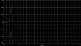
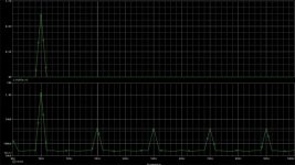
3) Thank you Steven for the tip on the crossover distortion, feedback won't remove it. Here is the sim output with a log plot for anyone who's interested.
Attachments
First a correct :
No. Base (and x beta Collector) current must flow.
This is one form of thermal instability, there are others.
It also implies a base current (collector current / beta)
which implies the base voltage > 0.6V.
QUOTE]Can you please suggest a 'decent textbook' that I should use instead?
Well the above book isn't wrong, as such.
Its referring to trying to set a collector current by holding
the base voltage without an emitter resistor - this is not
a good idea for lots of reasons, but a dead transistor is
certainly the the most cogent arguement against it.
Shows some of the limitations of the simulator.
No even harmonics -> transistor models are perfectly symmetrical.
This is pure conjecture born from ignorance, reality
has nothing to do with personal perspective.
Crossover distortion cannot be removed from real world Class
B amplifiers because of fundamental electrical principles.
(As outlined in my previous post)
No. Hot spotting causes the maximum allowable current to be
lower than the current implied by thermal limits at high currents.
Whilst hotspotting is a form of local thermal runaway (not the
other way round) it applies to any transistor in any circuit, if
it is operated beyond its current limits.
When discussing thermal runaway in circuit topologies the
reference is always to unstable DC biasing arrangements.
Not fast enough, because of fundamental electrical principles.
(Unless the simulator assumes the op-amp has infinite gain
and infinite speed, in this case its not much of a simulator)
sreten.
Class B by definition cannot suffer thermal runaway as it no DC bias.
Class B also by definition exhibits crossover distortion that cannot
be removed by any real world application of negative feedback.
(I'd just got up , class C slipped in instead of class B)
1) Is 0-volts at the base considered DC biasing if the load is referenced to ground?
No. Base (and x beta Collector) current must flow.
"... if Vbe is held constant and the temperature increases, the collector current increases. The increase in collector current increases the power dissipation which in turn increases the collector current. Thus a positive feedback mechanism exists that can result in thermal runaway."
This is one form of thermal instability, there are others.
It also implies a base current (collector current / beta)
which implies the base voltage > 0.6V.
QUOTE]Can you please suggest a 'decent textbook' that I should use instead?
Well the above book isn't wrong, as such.
Its referring to trying to set a collector current by holding
the base voltage without an emitter resistor - this is not
a good idea for lots of reasons, but a dead transistor is
certainly the the most cogent arguement against it.
Here is the sim output with a log plot for anyone who's interested.
Shows some of the limitations of the simulator.
No even harmonics -> transistor models are perfectly symmetrical.
It is, however, arguable (or unlikely depending on your perspective) that the same is true with real life circuits or simulations using reasonably good models.
This is pure conjecture born from ignorance, reality
has nothing to do with personal perspective.
Crossover distortion cannot be removed from real world Class
B amplifiers because of fundamental electrical principles.
(As outlined in my previous post)
i have always thought that thermal run-away is caused by hot spotting which may or may no thave anything to do with biasing.
No. Hot spotting causes the maximum allowable current to be
lower than the current implied by thermal limits at high currents.
Whilst hotspotting is a form of local thermal runaway (not the
other way round) it applies to any transistor in any circuit, if
it is operated beyond its current limits.
When discussing thermal runaway in circuit topologies the
reference is always to unstable DC biasing arrangements.
a much interesting plot would be to chart Vin, Vo and Pin 6 of the Opamp. You will see that the voltage on Pin6 crosses zero very fast (to reduce cross-over distortion at Vo).
Not fast enough, because of fundamental electrical principles.
(Unless the simulator assumes the op-amp has infinite gain
and infinite speed, in this case its not much of a simulator)
sreten.sreten said:fundamental electrical principles.
just curious. What are those "foundamental electricl principles" and how would they work in this case?
sreten said:(Unless the simulator assumes the op-amp has infinite gain
and infinite speed, in this case its not much of a simulator)
isn't that exactly what perfect opamps are?
I am sure you can work out a case in either formula or even excel to show precisely that.
again, what it shows may not have any bearing with real world experience, which I clearly outlined earlier.
Class B by definition cannot suffer thermal runaway as it no DC bias.
that depends on your definition of class b (no kidding here).
some people define class b as 180 conduction so for bipolar devices that would be some form of bias.
others define class b as no bias, which actually is called class C by the first group.
confusing as always.
if anyone is interested, I can post a pdf file from Fairchild on mosfet devices and their thermal behaviors (and how that differs from that of bjts).
you may also download it from fairchild directly. It is their application note 7500, "understanding power mosfet".
quite useful for mosfet aficionado.
you may also download it from fairchild directly. It is their application note 7500, "understanding power mosfet".
quite useful for mosfet aficionado.
millwood said:
just curious. What are those "foundamental electricl principles" and how would they work in this case?
Gain Bandwidth Product (GWP) (MHz) of the Op-Amp.
Slew Rate Limit (V/us) of the Op-Amp.
Compensation of Op-Amps for closed loop stability.
741 - 1MHz and 0.5V/uS - compensated for unity gain.
741 - 4MHz and 2.0V/uS - compensated for gains > 5.
With standard single pole compensation feedback falls at
6dB/octave (20dB/decade),
consequently the crossover distortion rises with frequency.
(741 unity gain compensated open loop gain starts
falling at ~ 10Hz at 6dB per octave, gain x F = GBP)
At 26dB ( = x20 gain typical for a power amplifier) GBP tells
us for a unity gain 741 there will be no feedback at 50K.
At 20K there will be 8dB, 10K 14dB, 5k 20dB etc.
Max feedback is 74dB below 10Hz.
Not only that : At ~1k crossover distortion components are
liberally produced right up to 20K and beyond. Standard 1 pole
compensation above the turnover frequency spectrally skews
these components increasing higher harmonics at 6dB/octave.
(less effectively reducing the harmonics at 6dB/octave)
Should be obvious the unity gain 741 is a very poor choice.
isn't that exactly what perfect opamps are?
there's no such thing as a perfect Op-Amp and its utterly pointless
discussing real Class B topologies with the assumption that they exist.
sreten.sreten said:there's no such thing as a perfect Op-Amp and its utterly pointless
discussing real Class B topologies with the assumption that they exist.
there is no such thing as a perfectly resistive resistor; nor a perfectly capacitive capacitor; etc. you cannot even find 100% water. but I sure hope we continue to talk about them as we have for the longest time.
BTW, I still have trouble understanding how your calculations relate to the topic.
millwood said:
there is no such thing as a perfectly resistive resistor; nor a perfectly capacitive capacitor; etc. you cannot even find 100% water. but I sure hope we continue to talk about them as we have for the longest time.
BTW, I still have trouble understanding how your calculations relate to the topic.
This is getting tedious,
sreten.Richard C said:In this case the definition of 'class-b' appears in the first post.
Thank you for highlighting this....
(I'd just got up , class C slipped in instead of class B)
No worries, now we're on the same page, thanks for the correction.
I think that we've reached a conclusion then. In the topology outlined (whatever it may be decided to be classified, I labeled it Class B per the definition in my textbook(s) ). Thermal runaway will not occur because a fixed bias isn't being applied. Other issues, which also exists in many other topologies, will still likely be of note such as device overheating.
Thank you everyone for your comments.
With respect to the feedback. Here is my perspective.
The feedback gain is: Ao / 1+ (Ao/B). We like to simplify this to 1/B which assumes that Ao is "significantly large". This is convenient because this means that even if Ao isn't a perfectly linear function (ie. has distortion), as long as it remains large, this equation will simplify still to 1/B.
However, at the crossover band, the Ao is not significantly large, it is 0 so that would suggest that feedback will not be effective in this range.
Actually now an interesting discussion would be, why is it then that feedback DOES do something to eliminate crossover distortion in this area when mathematically it shouldn't? Because it is delayed by the slew? Or maybe because the gain isn't truely modeled by a piecewise function.
--
Danny
Sound Quality
If NFB could fix crossover distortion, it would have been done years ago. Don't waste your time. A class B amplifier sounds like crap at lower power levels and they spend far more time at low power than high.
And, a class B amplifier that has heatsinks that are too small and which is driven hard can experience thermal runaway. Its a little harder than a class AB but it can be done.
Bias circuits with thermal feedback have been in use for over 30 years and thermal runaway is one of the easiest to fix problems in a power amplifier. On the other hand, crappy sound from trying to have NFB fix a pile of distortion is something that won't go away.
Re: Sound Quality
How? since it has no bias current won't it just cool down when the input signal is removed?
dmfraser said:
And, a class B amplifier that has heatsinks that are too small and which is driven hard can experience thermal runaway.
How? since it has no bias current won't it just cool down when the input signal is removed?
- Status
- This old topic is closed. If you want to reopen this topic, contact a moderator using the "Report Post" button.
- Home
- Amplifiers
- Solid State
- Will a true class B have thermal runaway?