When I placed a 220R across the L, it produces adequate voltage to the regulator. I just measured the current flow across the 220R, it shows 48mA. In this respect, the power is only around 0.5W but the resistor with a rating of 2W (Kiwame 2W) turns burning hot (over 100 degree C after 1.5 minutes). Why could this happen? Is over 100 degree C normal for resistor?
You need to carefully re-read previous comments about the AC and DC voltage impressed across your 220 ohm resistor.. And you need to do the calculations, but this is NOT the right approach.. The choke input is there for a reason - to provide a very high impedance between the mains, transformer, rectifiers and your phono stage. You really NEED a somewhat higher voltage transformer. You need the full reactance of your choke for isolation, shunting it that resistor solves the dc drop issue, but degrades the isolation for AC..
Resistors should not be run at excessively high temperatures, for a metal oxide take a look at the derating curve for a typical metal oxide power resistor. Wirewounds may be run hotter, but in general I don't like them to heat much beyond 70 degrees or so..
You speak about silver wire on a PS transformer as if the music it self travels through this basic component?
I picked up on that too.
The power supply usually makes little difference to the sound unless the PSU is running out of steam and/or has lots of ripple.
The choke is an expensive part, it's still providing isolation ie ripple reduction in the CLC topology. Nobody suggested removing it at this point, I don't agree with the OP shunting it with a resistor either. Now the OP is complaining the voltage is too high using my approach, maybe the OP should just stick with the original design and keep away from his woes with his mods, adding superduper silver wire on a LF power XFMR. BTW Most LC power filters suffer from underdamped response, actually making things worse at the corner frequency part of the spectrum. IMO the choke is an expensive, clunky low tech way of PS ripple rejection that a cleverly arranged CRC filter and good LN regulator would suffice. I'm sure if the OP posted the Vreg circuit we would see a low tech approach there as well.The choke input is there for a reason - to provide a very high impedance between the mains, transformer, rectifiers and your phono stage.
When I placed a 220R across the L, it produces adequate voltage to the regulator. I just measured the current flow across the 220R, it shows 48mA. In this respect, the power is only around 0.5W but the resistor with a rating of 2W (Kiwame 2W) turns burning hot (over 100 degree C after 1.5 minutes). Why could this happen? Is over 100 degree C normal for resistor?
Unless you measure the AC power across the resistor you don't know.
A power resistor is normally fine but still very hot at 1/2 of its rated dissipation. You can look it up on the data sheet. Depending on mounting this will / can discolor the FR4 fire rated PCB.
hi
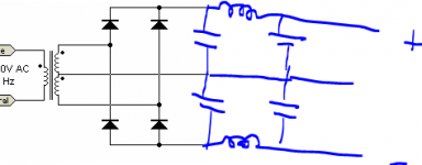
In order to use the CLC you need to use a CT XFMR, by connecting the 2 Pgnds together at the ouput. modify the rectifiers to use one diode per winding and watch the polarity of the windings. I think you need to reverse one secondary winding. The voltage will be very close to what you need.
In order to use the CLC you need to use a CT XFMR, by connecting the 2 Pgnds together at the ouput. modify the rectifiers to use one diode per winding and watch the polarity of the windings. I think you need to reverse one secondary winding. The voltage will be very close to what you need.
Attachments
I picked up on that too.
The power supply usually makes little difference to the sound unless the PSU is running out of steam and/or has lots of ripple.
I have a different experience in this issue. In this particular application, it started with a EI transformer, then upgrade to Plitron toroidal transformer and then to this OCC copper silver plated wire toroidal transformer. In the course of this changes, I can hear the difference, especially changing from EI to Plitron.
In another application - a CD transport using CDM12 mechanism, the change from a Chinese made toroidal (made by a joint venture between Hitachi and a Chinese firm) to Plitron brings day and night difference. Not only it is my experience, but also to 3 of my friends who are using the same CD transport.
I dont' know if the previous transformers are running out of steam or not but hearing is believing.
Last edited:
The Vreg is from Erno Borbely. Actually, I am using the full set of kits from him except I'm not going to buy transformers and chokes all the way from Germany to Hong Kong.
Phono amp - model 320
Vreg - model 255
The circuit of these models are available in his website. But sad to know he is closing down his business in this October. Fair enough, he has been working for 50-60 years and should take some rest and enjoy himself.
The EI transformer is a CT type rating at 1.5A each. The phono amp sounds better than my previous ASR Basis (10 years old model) and DACT CT-100 (using two DACT regulators). However, as a DIYer, you never satisfy and therefore I started to modify the PSU since I have very good experience when changing to use Plitron. The sales in Plitron Shenzhen is my classmate therefore he can make small quantities for me as sample (but still 10 pcs minimum). This is why I have specially made transfromer from time to time. Unluckily since last month, Plitron stopped supplying directly to China and all order, even sample order, has to go through Canada.
The Plitron transformer has 2 x 44V secondary windings rating at 1.5A each. Its superior quality out-performed my original EI transformer by great extend.
The new transformer also has 2 x 44V secondary windings rating at 1A each. The high is silky smooth even when compare to the using of Plitron. The sound stage is more clear and only the bass is a little bit less. Increasing the voltage brings back the bass.
In this respect, I think I will return the transformer to the manufacturer and ask him to give it more secondary windings to 48V AC. My concern is the quality of transformer by soldering a new wire to add the winds VS rewinding the entire secondary with one single piece of wire. Yet, after giving it a second though, it could be resembled to those multi-voltage transformer that has a numer of output voltage in the same secondary winding.
The only drawback is I have to bring the transformer back to China in my next trip and he can courier to me in Hong Kong when its done. I cannot use courier to China because of import tax (although it is made in China) problem. The cost to add more rounds to the two transformers is only about US$50 but it troubles me in bringing this back to China.
Last edited:
hi
In order to use the CLC you need to use a CT XFMR, by connecting the 2 Pgnds together at the ouput. modify the rectifiers to use one diode per winding and watch the polarity of the windings. I think you need to reverse one secondary winding. The voltage will be very close to what you need.
I am using this same circuit except I am using a transformer with two separate secondary windings instead of CT. Please refer to my posted circuit as above.
I am using this same circuit except I am using a transformer with two separate secondary windings instead of CT. Please refer to my posted circuit as above.
well it would help to post these things in the beginning. Read my post above, you need to pull out four diodes and jumper a few wires. Not too difficult. Easier than new transformer.
- Status
- This old topic is closed. If you want to reopen this topic, contact a moderator using the "Report Post" button.
- Home
- Amplifiers
- Power Supplies
- Why voltage dropped in my new transformer?