Hi,
I am struggling to understand the purpose of the 60 ohm resistor in this crossover:
I simulated it with "5 spice", I understand the purpose of the other elements, but this appears to reduce the attenuation of the woofer at high frequencies to just a few dB below the output of the tweeter? Is this for transient response? Doesn't it make one prone to hearing the effects of the cone break up?
thanks
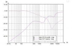
(ps. This comes from Mark K's speaker pages: The Seas ER18DXT ported two way
Looks like an interesting 2 way)
tx
I am struggling to understand the purpose of the 60 ohm resistor in this crossover:
I simulated it with "5 spice", I understand the purpose of the other elements, but this appears to reduce the attenuation of the woofer at high frequencies to just a few dB below the output of the tweeter? Is this for transient response? Doesn't it make one prone to hearing the effects of the cone break up?
thanks
(ps. This comes from Mark K's speaker pages: The Seas ER18DXT ported two way
Looks like an interesting 2 way)
tx
Last edited by a moderator:
Sorry - the image may not open - not sure how to post images - but you can see the crossover in the supplied link. It has a 1st order low pass filter with a notch filter at 5KHz added. The 60ohm resistor is across (in parallel with) the main inductor for the low pass filter. Why bother? Only affects the woofer at well above cross over right?
THANKS!
THANKS!
http://en.wikipedia.org/wiki/RL_circuit#Parallel_circuit
Seems like it reduces the strength of the low-pass filter and alters the phase of woofer.
Seems like it reduces the strength of the low-pass filter and alters the phase of woofer.
Last edited:
RL circuit - Wikipedia, the free encyclopedia
Seems like it reduces the strength of the low-pass filter and alters the phase of woofer.
Thanks Ruinevil - You are right - I hadn't looked at the phase closely enough around 2-5Khz cause the attenuation wasn't changing much there with or without that resistor - but is does change by 25deg or more in that frequ range. Though seems crazy to allow only ~ 5dB of attenuation relative to the high pass filter at 20kHz just to get that phase "correction" so I was wondering if that aspect of the design had some explicit purpose...
thanks
The 60 ohm resistor is more about the notch filter.
A shunt-connected, series RLC needs a series resistor element to create the voltage divider which yields the notch. The inductor itself becomes a series element when out of band, but this combination must have worked well for Mark.
A series-connected, shunt network would be an option also, but Mark's preference in this case was probably chosen because of impedance concerns.
Cheers,
Dave.
Last edited:
I am struggling to understand the purpose of the 60 ohm resistor in this crossover
The 60 ohms in parallel with a 2.5mH is a Bass Shelving Filter. Basically, it attenuates the higher frequencies.
Following that is a Notch Filter. There is no Conventional Crossover. The combination of this Shelving Filter and the Notch Filter serves as a crossover (blue trace in FR plot)
Well, what MarkK COULD have done is just put a 0.1uF capacitor in line with the 60R resistor, and finished the 10kHz (tank) notching of the rather good SEAS ER18RNX. That would have been a conventional sort of smooth 2nd order speaker with excellent phase alignment and no cone breakup worth mentioning. ")
But NO!!!
He decided to simulate all the HORRORS of a metal cone with it's breakup and midband phase problems. He set out his TARGET RESPONSE, and succeeded in implementing it.
Doubtless the cloth-eared brigade said it sure sounds GOOD and LIVELY like a low-order should and it's got flat "power response" apparently! And went home with their ears ringing...
The treble filter is frankly, equally baffling with its mainly random notches. But as I said to Mark, the Mark 2 version could be great. Really.
Attachments
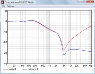
I don't think this is correct - I have done the simulations both with and without the resistor. The resistor REDUCES the high frequency attenuationThe 60 ohms in parallel with a 2.5mH is a Bass Shelving Filter. Basically, it attenuates the higher frequencies.
Following that is a Notch Filter. There is no Conventional Crossover. The combination of this Shelving Filter and the Notch Filter serves as a crossover (blue trace in FR plot)
thx
I believe the 5uf Cap in series with the 0.22mH inductor is actually the notch filter in this ckt.The 60 ohm resistor is more about the notch filter.
A shunt-connected, series RLC needs a series resistor element to create the voltage divider which yields the notch. The inductor itself becomes a series element when out of band, but this combination must have worked well for Mark.
A series-connected, shunt network would be an option also, but Mark's preference in this case was probably chosen because of impedance concerns.
Cheers,
Dave.
thx
Yes - but at least I knew they were notches and thus knew what was being attempted.The treble filter is frankly, equally baffling with its mainly random notches. But as I said to Mark, the Mark 2 version could be great. Really.
Just trying to learn a bit about crossovers by seeing what folks are doing and "reverse engineering" them to the extent I can - your comments were very helpful. ThxI don't think this is correct - I have done the simulations both with and without the resistor. The resistor REDUCES the high frequency attenuation
thx
I am correct and so are you. You may want to check up on the term "Shelving Filter".
I believe the 5uf Cap in series with the 0.22mH inductor is actually the notch filter in this ckt.
thx
Yeah, I know what the notch filter is.
Are you running your simulation with a real impedance plot of the ER18 driver?
Most of the shelving action is coming from the inductor itself.
The notch filter is tuned to 4.8khz and a 2.5mH coil will have Xl of about 75 ohms at that frequency. Thus the 60 ohm resistor in parallel becomes a significant portion of the notch action as well.
There's much interaction in that crossover. It's not really comprised of "sections" that would operate by themselves.
Hope that helps.
Cheers,
Dave.
Last edited:
Yes - but at least I knew they were notches and thus knew what was being attempted.
It's all a lot easier than people usually let on. Lynn Olson is the guy to read:
When working with rigid-cone drivers, there are some hard choices to make: if you lower the crossover frequency to minimize driver coloration, tweeter IM distortion skyrockets, resulting in raspy, distorted high frequencies at mid-to-high listening levels.
If you raise the crossover frequency to improve the sound of the tweeter, the rigid-driver breakup creeps in, resulting in a forward, aggressive sound at moderate listening levels, and complete breakup at high levels. (Unlike paper cones, Kevlar, metal, and carbon fibers do not go into gradual breakup.)
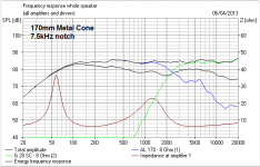
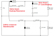
With the drivers we have today, the best all-around compromise is a 2nd, 3rd, or 4th-order (12-24dB/Oct.) crossover with an additional NOTCH filter tuned to remove the most significant HF resonance of the midbass driver.
That is exactly what I have done here:
An externally hosted image should be here but it was not working when we last tested it.
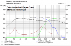
The Visaton G20SC Tweeter has an Fs of 1400Hz. The Visaton W170S Woofer has a first resonance at 5kHz. The natural crossover is the geometric mean of 2.8kHz. Second order happens to work nicely with these drivers, sometimes third order on tweeter helps. The higher 10kHz notch is just showing off really. Not strictly necessary.
Most (expensive) drivers that use very low order crossovers are flawed, and will work even better with regular techniques. Most serious designers are more interested in time alignment these days, where the drivers acoustic centres are kept aligned. This is fun stuff with sloped baffles and such.
A Joachim Gerhard design, the Anima.
An externally hosted image should be here but it was not working when we last tested it.
A diyaudio enthusiast called Michelino.
An externally hosted image should be here but it was not working when we last tested it.
Solves many phase issues.
Yeah, I know what the notch filter is.
Are you running your simulation with a real impedance plot of the ER18 driver?
Most of the shelving action is coming from the inductor itself.
The notch filter is tuned to 4.8khz and a 2.5mH coil will have Xl of about 75 ohms at that frequency. Thus the 60 ohm resistor in parallel becomes a significant portion of the notch action as well.
There's much interaction in that crossover. It's not really comprised of "sections" that would operate by themselves.
Hope that helps.
Cheers,
Dave.
Hi Dave -
I am using a spice model and I have put in 1/2 of the voice coil inductance (as a rough approximation of the lossy inductor) I sometimes have put in the equivalent ckt of the resonance from Rod Elliot (ESP) spread sheet from the Thiele parms but did not in this case because it should not affect things at the higher frequency much correct? I do know about FRD and ZMA files and have used Isaac MCN xoversim - but it is a bit cumbersome and requires one to have exactly the same # of data points for each driver in the system. (A recent responder to another question I had suggested Jeff Bagby's Passive Xover designer - I will try to learn that one, looks more versatile, any other suggestions for good software are welcomed)
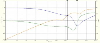
I see your point that the 60 ohms is a significant at the notch frequency but from a 10000 foot view it looks to me that the biggest change with the 60 ohm resistor is happening at higher frequencies and was wondering if that was a desired aspect of adding that resistor or just an acceptable side effect.
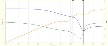
Attached (I hope - new to this forum stuff) are Mark's transfer function, the spice simulation I did (matches the main features pretty well to my eye) and then the simulation without the resistor.
Granted - some changes to phase and attenuation at the xover point and in the notch, but I guess my question is fundamentally - is that the best way to achieve the effects at xover and notch and was that the main intent of the designer or was he actually going for the reduced attenuation at the higher frequencies? (and if so - why?)
Thanks - I am learning more from each response!
Attachments
Granted - some changes to phase and attenuation at the xover point and in the notch, but I guess my question is fundamentally - is that the best way to achieve the effects at xover and notch and was that the main intent of the designer or was he actually going for the reduced attenuation at the higher frequencies? (and if so - why?)
I guess the designer wanted to achieve exact phase matching at the crossover frequency and accepted to give up 4 dB attenuation at the cone breakup frequency for that purpose.
Attachments
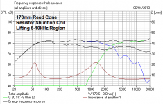
I was tought by my master that you can place a resistor in paralel with a 'too big' inductor
you use a 'too big inductor' to make it work early
and you use the resistor to slow it down a bit, giving it a more gradual slope, until it kicks in for real
but another big master said...never do that, it causes phase issues
no matter what, I never use that 'simple trick' anymore
you use a 'too big inductor' to make it work early
and you use the resistor to slow it down a bit, giving it a more gradual slope, until it kicks in for real
but another big master said...never do that, it causes phase issues
no matter what, I never use that 'simple trick' anymore
Most (expensive) drivers that use very low order crossovers are flawed, and will work even better with regular techniques. Most serious designers are more interested in time alignment these days, where the drivers acoustic centres are kept aligned. This is fun stuff with sloped baffles and such.
That's a bold statement to make if you don't know the design intends...
Your opinion, maybe not shared by all others.
The Visaton G20SC Tweeter has an Fs of 1400Hz. The Visaton W170S Woofer has a first resonance at 5kHz. The natural crossover is the geometric mean of 2.8kHz. Second order happens to work nicely with these drivers, sometimes third order on tweeter helps. The higher 10kHz notch is just showing off really. Not strictly necessary.
Thanks System 7 - I can follow what you are doing with this crossover. Also appreciate the comments about the merits and drawbacks of different cone types and how you take that into account in defining a system and designing the crossover.
thx
Most serious designers are more interested in time alignment these days, where the drivers acoustic centres are kept aligned. This is fun stuff with sloped baffles and such.
A diyaudio enthusiast called Michelino.
An externally hosted image should be here but it was not working when we last tested it.
Solves many phase issues.
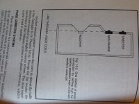
These set back designs are very interesting and I had thought I saw something like it before. Indeed - I found this in Weems' 1978 book (see image below).
Looks like this idea has been out there for a while - what I wonder is;
Is it worth doing such offsets in a "tower" design such as the Sunflower -
(link from Fastbike: https://sites.google.com/site/undefi...diy-sunflowers)
where one already made the tradeoff to violate keeping the CTC of woofer to the Mid within a fraction of a wavelength? (or are you already going to have to fix the phase alignment with the crossover - so no point lining up the voice coils?)
Attachments
- Home
- Loudspeakers
- Multi-Way
- Why resistor in parallel with inductor in low pass crossover?