OK. Let's have a look at the most theoretically perfect speaker on the Planet.
That is open to dispute. It is just a different set of compromises.
dave
Actually it would suffice if manufacturers began to offer good and real data for phase correction. Or if they want to keep their data somewhat hidden, offer a free plugin that does phase correction for their speaker for those who care. A very cost-effective and easy solution both for the makers and the users. Some companies in the studio monitor scene start to offer this kind of add-ons for those who care. Audibility of group delay is still debated but it seems clear that while it can be audible it's not a deal breaker. Most speaker designers feel that compromising a speaker in other areas for the sake of transient-perfectness might not be a good idea, especially with the tools available for global phase-correction via FIR-preprocessing the source signal. Phase correction is almost a non-issue these day technically, what's missing is a simple plug&play implementation for the average user.If you knew what the target loudspeaker is, you could doubtless manufacture a CD with a prealigned phase or group delay correction for perfect impulse response. Unfortunately every loudspeaker is different, so it wouldn't be one size fits all. Perhaps Apple could make the MacSpeaker and then we would all have to buy MacCDs?
Which are?we see lots of pushing over the boundaties and people forgetting the limitations.
If you add a small signal to a large signal it isn't buried, you will be able to see (on an oscilloscope) and hear it. There is no mystery, it's very basic stuff, you must know that, am I misunderstanding what you are saying?
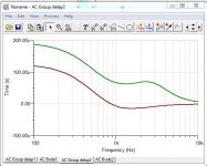
Let's talk more about group delay.
Bafflestep adds some. So does steeper 4th order reflex bass.
Now I CAN hear the delay in reflex over closed box. It loses timing. I tap my feet more to closed box.")
Add the issues of dispersion and wall mounting and room gain, and it gets quite complicated. That's why people get confused. Me, I understand all of it.
The room is the monster.
Bafflestep adds some. So does steeper 4th order reflex bass.
Now I CAN hear the delay in reflex over closed box. It loses timing. I tap my feet more to closed box.
Add the issues of dispersion and wall mounting and room gain, and it gets quite complicated. That's why people get confused. Me, I understand all of it.
The room is the monster.
Attachments
Which are?
If you add a small signal to a large signal it isn't buried, you will be able to see (on an oscilloscope) and hear it. There is no mystery, it's very basic stuff, you must know that, am I misunderstanding what you are saying?
You could add a small signal and it's buried! That's how hearing loss works;o)
OK. Let's have a look at the most theoretically perfect speaker on the Planet.
It's the Steen Duelund Filter.
Duelund was the Einstein of speakers. Because he designed something that works for ANY speaker. He wasn't interested in the details.
Nevertheless he drew some interesting conclusions. I could go into it. But you know all this stuff, don't you.
We have currently reached A= 2 root 2, IMO.
SBAcoustics-3WC
Where did you get those pictures? There appears to be many mistakes in the content. Why does the tweeter phase go to -360 at the highest frequencies? It should be near 0. Also, there's nothing special about linear phase on a log frequency scale. There's nothing linear about that.
The sum is a 2nd order allpass function, that's why (and don't mind a static 360° offset). The Duelund XO has similar properties like a LR4 except that there is a mid filler-driver that can be blended into the mix in various amounts.Why does the tweeter phase go to -360 at the highest frequencies? It should be near 0.
While a good idea, the Duelund XO is not that special after all (J.Kreskosvky has a paper about it) and it isn't that useful in practice because the mid bandpass is only 4th order, 2nd order target slopes don't cut it in my book.
If there is any interest I can upload a LTspice sim of the Duelund.
@System7: ANY competent speaker designer comes up with solutions that can be applied to any speaker. At least when he's got a profound knowledge of linear system theory and special skills in transfer function manipulation. Back in the day this was harder because everbody tried to solve things analytically which turns out to be a dead end, many useful approaches are missed by this. I have no disrespect for guys like Duelund, Hawksford, Kreskovsky et al., quite the contrary.
Last edited:
Duelund articles at the following link especially duelund-filter.pdf, aka as "The art of building a loudspeaker to the end.
By Steen Duelund":
Articles by Mr. Steen Aa. Duelund – Duelund Coherent Audio
John Kreskovsky has a good look at it here: Duelund and Beyond.
Steen was very clever in realising that a two way is just a three way with the mid turned right down.
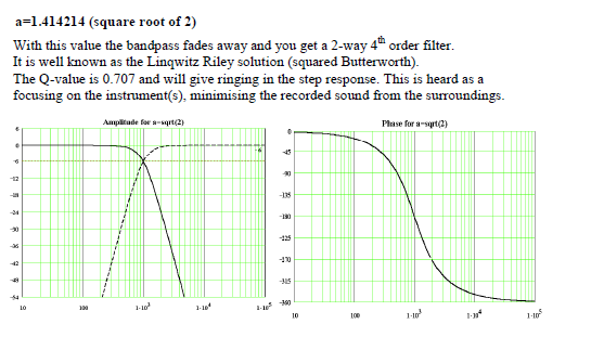
If you look at the best of the classic 3-ways, you find they are pure Duelund target slopes.
They are not linear phase, because group delay comes with any real filter as the arrow of time in our universe. There are some solutions that achieve linear phase, but the demands on the midrange driver make it difficult to implement. Duelund is more about phase aligned at all frequencies for all drivers. This is largely doable. Tweeter phase shifts 360 degrees because these are near 4th order LR4 filters.
You will see that Troels' latest squeeze has a Duelund target response.
SBAcoustics-3WC
Seems to work for second order LR2 slopes too, but I haven't given that much thought.
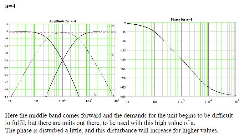
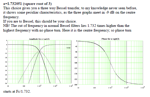
As midranges get better, and SEAS, SB Acoustics and Scanspeak make some stellar flat 4" jobbies these days, we might get closer to Steen's A=4, which improves the group delay further. There are some BW3 solutions, but I am starting to get a headache now.
Just teasing you really, but given that everybody here knows everything, we sure get a lot of dumb designs... I must be missing something.
By Steen Duelund":
Articles by Mr. Steen Aa. Duelund – Duelund Coherent Audio
John Kreskovsky has a good look at it here: Duelund and Beyond.
Steen was very clever in realising that a two way is just a three way with the mid turned right down.
If you look at the best of the classic 3-ways, you find they are pure Duelund target slopes.
They are not linear phase, because group delay comes with any real filter as the arrow of time in our universe. There are some solutions that achieve linear phase, but the demands on the midrange driver make it difficult to implement. Duelund is more about phase aligned at all frequencies for all drivers. This is largely doable. Tweeter phase shifts 360 degrees because these are near 4th order LR4 filters.
You will see that Troels' latest squeeze has a Duelund target response.
SBAcoustics-3WC
Seems to work for second order LR2 slopes too, but I haven't given that much thought.
As midranges get better, and SEAS, SB Acoustics and Scanspeak make some stellar flat 4" jobbies these days, we might get closer to Steen's A=4, which improves the group delay further. There are some BW3 solutions, but I am starting to get a headache now.
Just teasing you really, but given that everybody here knows everything, we sure get a lot of dumb designs... I must be missing something.
Now I CAN hear the delay in reflex over closed box. It loses timing. I tap my feet more to closed box.
Things that have influence on my foot tapping:
Actual musical contents 100%
Type or quality of speaker, crossover, amp etc 0%
If you knew what the target loudspeaker is, you could doubtless manufacture a CD with a prealigned phase or group delay correction for perfect impulse response
This is something I was wondering about for a longer period of time. For example i choose to make a elactive speaker with IIR based filters, giving the benefit of no to little time delay, but in some applications I would like to have a lineair phase and a (approximatly) perfect impulse response. Can I do that by just adding a FIR filter in front of the speakers correcting for their phase differences.
And if ilI do so, what is the benefit/downside of designing the speakers with FIR filters from te start.
Hope that my question is clear enough, otherwise I would love to elaborate it more
@Tom155, check out the RePhase thread, it probably answers a lot of questions you have right now.
There are more ways to do the same, but the RePhase thread would be a good place to learn. Other examples are using software like Audiolense or Acourate. Both of these tools are commercial products, with a lot more work one could get close to the same results using the free DRC-FIR.
Maybe a warning would be fair, there are different paths for each solution. One can correct the speaker, like Mark100 tried to get across here, the latter solutions I linked try to solve some room dilemma's too. But not without using common sense and room treatment. DSP should not be seen as a magic part that can cure everything. It can enhance your results though, if used wisely.
Last edited:
Tough crowd
Controversial thread titles seldom are a good idea I guess. And you're posting about a controversial subject as well.
I hope the people that posted on this thread, claiming they can do as good with IIR will share the results and details how they got there. What good is the claim to have it, if you don't share how it's done. I suppose that would have been your next move, if there were any interest?
I hope you do share what you did and how you got those results, there's always people watching (and learning). There will always be contradictory views as well.
Hi wesayso, thanks for your interest and kindly worded thoughts.
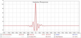
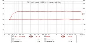
The measurements I posted were about as simple a setup as one could make.
It's pink noise split into 4 passbands by a DSP processor,
then the 4 passbands are all summed back together with a mixer.
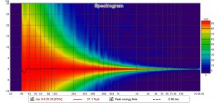
The summed output is measured against the original signal, transfer and impulse.
I use Smaart to measure, but REW would surely work just as well using a loopback reference.
It's a very easy experiment to see the definitive effects of x-over topology alone.
The opening screen shot of the x-over freqs is from the processor used, a Danley SC 48 ( rebadged Linea Research ASC-48).
It has what Linea calls LIR filters which are essentially linear-phase HP and LP filters that replicate the shape of 4th order LRs.
This processor makes comparisons easy, because it allows the LIR filters frequency to be adjusted on the fly, and it automatically gets delay right between the passbands.
So it's just a matter of changing x-over types, freqs, and measuring.
For others who are maybe interested in this kind of measured comparison , rePhase or any FIR software, and any FIR capable processor (miniDSP, etc) or PC convolution (jriver etc), is a good way.
Just sum the outputs and measure
It can get a little tedious building the FIR files, for all the various x-overs you might want to look at, be they IIR or linear-phase, but it totally works.
It's what I use for studying higher order slopes.
Hope that all was clear !
KO in second round! Good for you, bad for the naysayers;o)
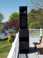
Please, show the four way!
Hi peterbrorsson !
Thanks for the moral support
I really don't want the thread to swerve towards a 4-way system I'm working on, but FWIW here is a picture of current efforts...along with a continually developing system impulse...
Attachments
Tweeter phase shifts 360 degrees because these are near 4th order LR4 filters.
The tweeter output shifts 360 degrees, but it is in phase (and cycle) with the input at higher frequencies where the capacitor impedances go to 0, and the inductor impedances go to infinity*i. I see that Dueland labels his charts with "phase" rather than "phase shift", so it is technically correct. I wonder how he would portray 720 degrees of phase shift. Would it wrap at 360?
Hi peterbrorsson !
Thanks for the moral support
I really don't want the thread to swerve towards a 4-way system I'm working on, but FWIW here is a picture of current efforts...along with a continually developing system impulse...
Oh no! I can hear the pre and post ringing even in my laptop! Wait, I had the in built speakers off...
Please continue to post info with measurements as xkr, byrtt, wesayso etc...
Ignore the other loudmouths
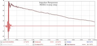
Can you also post a step-response ?
Regards
Charles
Hi Charles, sure.
I've added a couple more plots, but again, I'd kinda like to keep my particular building efforts out of the mainstay.
I was thinking....what if I took the opening comparison of the electrical x-over comparison a step further....
...and measure the 4-way speaker itself using the linear-phase xovers vs LRs as in opening post, keeping all other things equal .....??
I'll try to make this happen with the 4-way system in the picture,
and then share the plots...
Attachments
Thats too good, How does eq curve look like?
Hi manninen,
You know, FIR traces do often look so good, I've learned you have ask for off-axis in addition, to know you're not getting "tuned to a spot".
Off-axis traces are of course never as perfect looking, but they still look better that 95% of most of the on-axis stuff we see, IMHO,....especially if the measurement used for tuning is an average of multiple mic locations
I don't know exactly what FIR files I used on exactly what 4-way I was measuring in the prior post (i have a modular 4-way that allows interchanging different subs, mid boxes, and compression driver/horns....and I don't label measurements well enough as i try a bunch of combinations....but they all measure pretty much the same when dialed in)
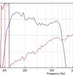
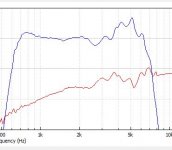
Anyway, here are typical curves in the FIR processor for the mid section (120Hz to 650Hz) and HF section (650Hz to 6300Hz). As both EQ and x-over are embedded in the FIR file together, they can't be separated into EQ alone.)
IMO, one of the major benefits of FIR is the ability to embed nearly infinite IIR EQs into the FIR file for minimum phase driver correction prior to xover.....so we can have EQ curves as precise and matching as these examples.
Attachments
Last edited:
- Status
- This old topic is closed. If you want to reopen this topic, contact a moderator using the "Report Post" button.
- Home
- Loudspeakers
- Multi-Way
- Why passive is passe ;)