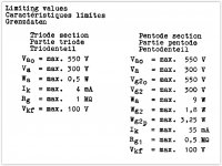
ECL86 pentode is rated for 0.5Meg max Rg1.
http://www.mif.pg.gda.pl/homepages/frank/sheets/030/e/ECL86.pdf --- page 4
This plan shows 1 whole Meg. And moreover a pot, which is typically low-tolerance (could be 1.3Meg easy). And pots can crack, go open.
I think the designer got too brave.
A quick-fix would be to tack a 1Meg grid to ground. Nominally that makes 0.5Megs, and 1Meg worst-case. I do not think it would be a major screw-up with tone or frequency response.
OTOH, it it is not happy with ~~1Meg, 0.5Meg is not a lot better. The tube may just be gassy. If the gas does not clean-up (or the tube burn-up) in a few hours, it should be replaced.
For fixed bias. It says that you can relax this requirement to the extent that the bias arrangement gives DC negative feedback. Hence for cathode resistor bias I would guess that 1M is the limit. Going to the limit on a valve rating is rarely a good idea, so I would use 0.5M. This may still be too big for a gassy valve.PRR said:ECL86 pentode is rated for 0.5Meg max Rg1.
For fixed bias. It says that ....
I do not see that in Philips 1962.
I _do_ see it in Philips 1970.
Not clear what "DC feedback" means here. Cathode bias usually allows 2:1 relaxation. The note suggests 20:1 difference. This almost smells like sticking a transistor (constant current source) under the bottle?
Also as has been said, the shared cathode bias invites see-saw failure: one tube goes cold, the other hot.
IAC, the posted plan is past or mighty-close to the ratings, ratings which may not have foreseen the product surviving 50+ years. If it is still beloved decades later, may be time to go more conservative?
Question to DF96 and others with the necessary experience: In a gassy tube, does the anode current keep rising with temperature/time as in run-away, or does it only give a higher than normal (constant) current? While I have limited experience of gassy tubes (perhaps I was fortunate!), I always assumed (experienced??) the latter regarding higher-that-spec readings on a tester.
It can run away as soon as starts conducting.
How does the getter flash look on the glass?
Whether thermal runaway happens and how quick it happens depends on bias arrangements and the grid leak resistance value. I guess it will also depend on cooling arrangements. Some valves are known for being prone to runaway; typically small power valves from the latter end of the valve era which ran with very hot glass.
.... and just to make matters cosy and reliable: Over the last decade I have measured a startling + /- 30% variation in tube specs (gm) with mainly eastern brand tubes that were obtainable down here. While that is more the limit than general, +/- 20% is quite regular.
What then drifts from what to where ....
What then drifts from what to where ....
Last edited:
same thing all over again, grid r is just too much.Schematic with added notes included as attachment.
The problem is that the cathode bias changes over time. During tests, the voltage rises, from 6.5V to 10V and presumably beyond. I disconnected the .01 uF coupling cap between one of the gain stages, to confirm whether there was DC present across the cap. The cap is fine with no leakage. I also checked the treble control to make sure the grid was still referenced to ground, and it tested fine and with a path to ground.
Both V5b and V6b tubes have a positive grid voltage with respect to pin 4/gnd. When each grid (still talking about V5b and V6b) has been tied to gnd with an alligator clip and wire, the cathode bias returns to something normal, between 6V and 6.5V.
Could the tubes be bad? They test well in a tube tester, though I haven't left the tubes in the tester for 10 minutes to warm up and see what happens. The power tubes are ECL86 pentodes.
Thanks. Happy Holidays.
 it seems the company violated the datasheet
as tubes age, emision material evaporates all over tube elements.
for example, why micas are rough surface, to minimize negative effects
since this tube has hi-steepness, grid will be very close to cathode and grid wires will be coated by some emission material already
add heat, and emission from grid is very likely.
you must go below 0,5meg
Attachments
Aargh! This is getting irritating (not the replies; the situation!).
Okay Tank,
You have two variable resistors between both pins 8 and earth - the treble controls. I suggest that you short the moving terminals (those going to the caps) to earth (no damage can occur). Then turn them to max and turn on the amplifier. Then measure the voltages on the respective pins 8 while turning first one pot down to zero and then the other (or are they ganged?).
You could probably measure what goes on more accurately on the tube cathodes, but they are tied together - never mind. The purpose is to find to what undesirable degree the positive pin-8 voltage is related to the pot position: Linearly, does it suddenly disappear near earth or what? (You have already determined that matters are approximately normal when those grids are both at earth potential, which they should also be with the treble controls at their zero end - okay, a 1K resistor is still in the circuits, but that should have no noticable effect.) By juggling you can also determine whether the two treble pots have the same effect (if they are not ganged) - watch the common cathode potential.
.... and if this has no effect, we really have a puzzle!! But one thing at a time.
and sorry if we appear to push you around; it is difficult to reach conclusions without the instrument in front of one!
Last edited:
Recap: ECL86 tubes replaced
I wish I had the chance to read pages 2 and 3 on this forum before finishing the amp. I replaced the tubes and everything was gravy.
I think I understand that gassy, used tubes attract more electrons to the control grid. Many clients that bring in Grundigs have sufficient "financial headroom" to buy $40 output tubes. If I see this amp again, I will have it in my notes to add a 1M across the treble controls, and replace the series high-pass filter caps with double the capacitance value so that I maintain 1/2piRC. I would also add independent cathode resistors.
I will also add these tips about the cheaper ECL86 and magic eye equivalents, provided that I can adjust the heater voltages accordingly.
Happy New Year. I'm building a Heathkit W-5M, nearly from scratch!
Not quite. Gassy valves can deposit positive ions on the control grid and that is what makes them go positive. Alternatively, a contaminated grid can emit electrons.I think I understand that gassy, used tubes attract more electrons to the control grid.
- Status
- This old topic is closed. If you want to reopen this topic, contact a moderator using the "Report Post" button.
- Home
- Amplifiers
- Tubes / Valves
- Why is my control grid going positive after 5 min. warmup?