The CF has its cathode riding on the audio signal. That same audio signal is applied to the CF grid, but now at half the voltage. As a result the CF stage has no longer unity gain but amplifies while output impedance is still low. Is that correct?
No, because you have essentially 100% feedback. The gain stays nearly constant - at least in the case of a light load. The follower is very lightly loaded in this circuit until the grid draws current. Even at high frequencies, the load is low. This is especially true for music as there is little content above 10k.
Sheldon
I think the source of the question is the cap that couples half of the first stage's signal to the cathode of the follower. Surely, this will affect the gain of the system, no?
There is 100% feedback in a standard cathode follower, but this is something different than a standard CF.
There is 100% feedback in a standard cathode follower, but this is something different than a standard CF.
Member
Joined 2009
Paid Member
The CF has its cathode riding on the audio signal. That same audio signal is applied to the CF grid, but now at half the voltage. As a result the CF stage has no longer unity gain but amplifies while output impedance is still low. Is that correct?
The cathode follower has a little less than unity voltage gain, but does have current gain since the current flowing into the load can be larger than the current flowing into the grid.
By the way, I don't think this circuit is the right approach.
The CF does buffer the input tube from the miller capacitance of the 2A3 grid, extending the high frequency slew rate of the amplifier despite the use of a wimpy input tube. But then the whole circuit makes no sense. The main reason to burn 10W to 15W in the 2A3 cathode resistor in the L-W circuit is to allow dc coupling of the input tube to the 2A3 grid. If you use a CF in-between then you may as well have a capacitor coupling between the input tube and the CF, give up the 500V of B+ and stop wasting heat in the 2A3 cathode resistor. Even better, replace the CF with a source follower for much better performance. This circuit (Sheldon borrowed it from Darius) seems like a redundant approach to me.
In my opinion, the main advantage of dc coupling is not to remove the 'sound' of a coupling cap but to remove blocking distortion which is going to occur in a low power amplifier due to it's limited dynamic range. And people who don't like capacitors because of fears of their 'sound' usually don't like CF's either. If you don't mind a cap coupling then the cathode/source follower will prevent blocking distortion.
Last edited:
The cathode follower has a little less than unity voltage gain, but does have current gain since the current flowing into the load can be larger than the current flowing into the grid.
But it is driving the midpoint of the first stage's plate load through that extra cap. So you could say, as disco did, that it has more than unity gain. Or you could say that it is increasing the gain of the first stage, or you could say that a positive feedback loop increases the gain of the system.
So there is positive feedback. This will increase distortion, Zout, and gain. It will still probably have a lower Zout than if you drove it directly from the plate of a 6SL7 CC VA stage.
I think there are ways to do it better, but to each his own.
I think the source of the question is the cap that couples half of the first stage's signal to the cathode of the follower. Surely, this will affect the gain of the system, no?
Yes. The bootstrap configuration makes the current across the final plate resistor effectively constant. Which means that the load line on the input tube effectively horizontal - which also, by the way, reduces distortion in this stage.
Sheldon
But it is driving the midpoint of the first stage's plate load through that extra cap. So you could say, as disco did, that it has more than unity gain. Or you could say that it is increasing the gain of the first stage, or you could say that a positive feedback loop increases the gain of the system.
As noted above, it does increase the gain of the first stage - but not by positive feedback. That's something quite different.
Sheldon
By the way, I don't think this circuit is the right approach.
Right, wrong? Is this a religious argument? If we are going to approach it that way, then why is it "wrong"?
But then the whole circuit makes no sense.
?? The point of this circuit element is to increase the linearity of the input tube both with respect to the plate load and the frequency dependent load of the output tube.
If you use a CF in-between then you may as well have a capacitor coupling between the input tube and the CF, give up the 500V of B+ and stop wasting heat in the 2A3 cathode resistor.
So a bootstrapped follower has the same sonic characteristics as a coupling capacitor?
Even better, replace the CF with a source follower for much better performance.
Yes, or a bootstrapped source follower. But much better? Technically? Cost? Sounds better? Measures better? Looks better? What's the point of these ancient tube devices anyway?
In my opinion, the main advantage of dc coupling is not to remove the 'sound' of a coupling cap but to remove blocking distortion which is going to occur in a low power amplifier due to it's limited dynamic range.
And what about the original objective in this design of eliminating hum from a simple power supply? Of course, this is not the only way to solve that problem. But I don't recall such assertions.
people who don't like capacitors because of fears of their 'sound' usually don't like CF's either. If you don't mind a cap coupling then the cathode/source follower will prevent blocking distortion.
Generalized fear of caps or cathode followers is equally silly. Not all caps in all positions have the same effect. The same applies to followers. Caps don't have sound, nor do followers. Only the system has a sound, including speakers, room, ears, and brain.
I personally find the design an elegant overall approach to a SE tube amp of a certain type. Better, worse? The result sounds good to me and satisfying to understand and build. Whatever floats your boat.
Sheldon
Last edited:
As noted above, it does increase the gain of the first stage - but not by positive feedback. That's something quite different.
Sheldon
I don't know, Sheldon, we may be getting into the weeds of semantics here, but it is a feedback path that increases gain of the system. In my mind, that is the definition of positive feedback. It may be a clever and interesting way to use positive feedback but that's still what it is.
What this design does is trade some linearity of the CF to help increase linearity in the first stage.
The CF has a DC load of 100k but it has an AC load of about 33k at 20kHz due to the miller capacitance of the 2A3 and the capacitive coupling to the first stage resistors. This will cause the CF to hard clip at 39V peak(on the negative side of the swing) of output at 20kHz.
This is a design that barely eeks by in a lot of ways. It looks like the designer carefully optimized everything to get the most out of that 6SL7. It is not the way I would do things (I would just CCS load the first stage and use a mosfet to drive the 2A3) but like I said, to each his own. I can respect that the designer put a lot of thought into the design, but I'd want to build something that had a little more margin myself.
Last edited:
I don't know, Sheldon, we may be getting into the weeds of semantics here, but it is a feedback path that increases gain of the system. In my mind, that is the definition of positive feedback. It may be a clever and interesting way to use positive feedback but that's still what it is.
It's certainly not feedback in any standard meaning of the term in electronic circuits. If we just ignore definitions and use them any way we like, then they lose their utility.
There is no feedback around the input tube. If you use positive feedback in that accepted definition, you form an oscillator. The loop here, if you want to look at it that way, is to eliminate any AC difference across the final plate resistor. That's all the capacitor does. In that sense it's more like negative feedback (about 96% of the AC across that resistor is eliminated in this case - a function of the near unity gain of the follower).
What this design does is trade some linearity of the CF to help increase linearity in the first stage.
The CF has a DC load of 100k but it has an AC load of about 33k at 20kHz due to the miller capacitance of the 2A3 and the capacitive coupling to the first stage resistors. This will cause the CF to hard clip at 39V peak(on the negative side of the swing) of output at 20kHz.
I doubt it will clip "hard". But I haven't built this version. You might ask goldenbeer, who has simmed it, or soul merchant, who has built it. In any case, we are talking about music, not a lab instrument. If you are clipping music at 20kHz, you are clipping lower frequencies much more (or you are listening to very strange music).
This is a design that barely eeks by in a lot of ways.
That's true, in the sense that the design has limited degrees of freedom with which to fit each element into an appropriate operating range. Once done, however, it's operation is very stable. If eeking by means doing what it needs to do, and do it well (you get to decide what that means), then I agree.
I can respect that the designer put a lot of thought into the design, but I'd want to build something that had a little more margin myself.
No argument. I'm only reacting to undefined terms like good, bad, worse, barely, etc., applied as generalizations. The question is; what are your objectives, and does the final design meet them? If it does then it's good, if not, it's bad.
Sheldon
It's certainly not feedback in any standard meaning of the term in electronic circuits. If we just ignore definitions and use them any way we like, then they lose their utility.
There is no feedback around the input tube. If you use positive feedback in that accepted definition, you form an oscillator. The loop here, if you want to look at it that way, is to eliminate any AC difference across the final plate resistor. That's all the capacitor does. In that sense it's more like negative feedback (about 96% of the AC across that resistor is eliminated in this case - a function of the near unity gain of the follower).
Sheldon, it is certainly not true that positive feedback categorically results in oscillation. Heck, all of the old McIntosh Unity-Coupled designs use positive feedback in the bootstrapped drivers.
And you are coupling the output of the CF to the input of the CF in phase and in an amount that is greater than it would otherwise be without the coupling cap. This is positive feedback, the Electrical Engineer's definition.
If the node connecting the two 200k resistors were not coupled to the CF, that node would have half of the plate swing of the first stage there. With the output of the CF coupled to that node, almost the full plate swing appears there. This in turn causes slightly more drive to appear at the grid of the CF (since the gain of the input stage went up due to the more horizontal load line).
The gain of the feedback loop is small (and therefore the loop is stable and not prone to full blown oscillations) but it is feedback and it is positive, since the feedback signal is in phase with the input signal to the CF.
Like I said before, this trades some CF linearity for increased input stage linearity. The designer of this amp did not discover how to get a free lunch.
I doubt it will clip "hard". But I haven't built this version. You might ask goldenbeer, who has simmed it, or soul merchant, who has built it. In any case, we are talking about music, not a lab instrument. If you are clipping music at 20kHz, you are clipping lower frequencies much more (or you are listening to very strange music).
Your comment about clipping lower frequencies much more is incorrect. The DC load for the follower is a 100k resistor. The AC load is the plate resistors of the input stage, the 100k resistor, and the miller capacitance of the 2A3. It's the miller capacitance of the 2A3 that will cause clipping at high frequencies because the impedance will fall to about 100k at 20 kHz. Put that in parallel with the 100k resistor and the input stage resistors to find the AC load. It is a steep one for this 6SL7.
I probably underestimated the impedance of the input stage resistors since one will be bootstrapped to the plate of the triode, so will have a higher impedance, but I also didn't account for any stray capacitance. Still my estimate was a bit pessimistic (it is always good to err on that side rather than not pessimistic enough). Still, the SF will clip on the negative swing at higher frequencies because it cannot go below zero current and the AC load is much harder to drive than the DC one.
If I had to guess, I would say that the CF could probably drive the 2A3 to cutoff at 20 kHz but man it is close to not being able to. It certainly couldn't do it at 25 or 30 kHz, and it is going to be rolling off somewhat before 20 kHz, so it is just not how I would do it. I like to have a bit of margin here to keep the amp nice and flat out to 20 kHz.
The picture gets much better for the CF at lower frequencies because the impedance of the 2A3 miller capacitance is much higher at lower frequencies, so there is a lighter AC load on the CF at low frequencies.
To put things into perspective, the linearity of the input stage is vastly improved, while any loss in linearity of the CF is totally negligibe.Like I said before, this trades some CF linearity for increased input stage linearity. The designer of this amp did not discover how to get a free lunch.
The two real downsides of this arrangement are a little phase shift because of the feedback path thru the bootstrap cap, and reduced output impedance of the CF. With the loads presented here however, these are also not noticeable in this arrangement, so yes we kind of get a free lunch
")
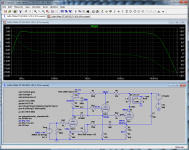
No need for guessing. The CF is able to drive the 2A3 far beyond 100kHz here (ignoring OPT effects). Frequency response in the audio range is really only limited by the OPT.If I had to guess, I would say that the CF could probably drive the 2A3 to cutoff at 20 kHz but man it is close to not being able to. It certainly couldn't do it at 25 or 30 kHz, and it is going to be rolling off somewhat before 20 kHz, so it is just not how I would do it. I like to have a bit of margin here to keep the amp nice and flat out to 20 kHz.
When simulating a perfect OPT, the loss at 45kHz is <0.01dB.
When simulating a perfect OPT, the loss at 45kHz is <0.01dB.
Could you please share your simulation file? I am not getting anywhere close to the above result.
The trouble was that back in the day they could only listen to the quality of an amp.
We now have the benefit of computer simualtion and spectrum anylisers so we can judge the quality of a design without having to use our ears.
Good joke!
Your comment about clipping lower frequencies much more is incorrect.
Perhaps I was too obtuse. My point was that the musical peaks are typically much larger at lower frequencies, therefore clipping at 20kHz - as a practical matter - is much less of an issue.
Sheldon
Originally Posted by ColinA View Post
The trouble was that back in the day they could only listen to the quality of an amp.
We now have the benefit of computer simualtion and spectrum anylisers so we can judge the quality of a design without having to use our ears.
Is mere speculation more predictive than simulation then? To my knowledge, soulmerchant is the only forum member who has actually built and heard this version (oldeurope is no longer active here). I've built a version of the L/W without a bootstrapped follower. We are both satisfied with the result. That doesn't make us "right" or "wrong" or this design "better" or "worse". But it is real world data.
Sheldon
The trouble was that back in the day they could only listen to the quality of an amp.
We now have the benefit of computer simualtion and spectrum anylisers so we can judge the quality of a design without having to use our ears.
Good joke!
Is mere speculation more predictive than simulation then? To my knowledge, soulmerchant is the only forum member who has actually built and heard this version (oldeurope is no longer active here). I've built a version of the L/W without a bootstrapped follower. We are both satisfied with the result. That doesn't make us "right" or "wrong" or this design "better" or "worse". But it is real world data.
Sheldon
Last edited:
Thanks, but could you provide the Spice models for the 6SL7 and 2A3, I am sure they are causing the discrepency between the sims.Here you go.
Member
Joined 2009
Paid Member
Right, wrong? Is this a religious argument? If we are going to approach it that way, then why is it "wrong"?
It looks wrong as in wrong-headed engineering. Once you put a CF between input tube and output tube you no longer need to waste all that power in the output tube Rk, or pay for high voltage capacitors for the h.t. supply. Just cap-couple the input tube to the CF driver and reduce your h.t. voltage. You can still use the L-W noise cancellation and still use the bootstrapped load for the input tube anode.
attached.Thanks, but could you provide the Spice models for the 6SL7 and 2A3, I am sure they are causing the discrepency between the sims.
Attachments
- Status
- This old topic is closed. If you want to reopen this topic, contact a moderator using the "Report Post" button.
- Home
- Amplifiers
- Tubes / Valves
- why do wimpy drivers for 2A3 work as well as they do?