Some of this is age. I have some TC Sounds fifteens that over a decade old, and their Q has gone up noticeably over the years.
The high Q of tube-era AlNiCo speakers is caused by 2 factors- weak cheapo motors (just as now, there are good and bad, AlNiCo can be undersized just like neo or ceramic)
AND
Demagnetization due to excessive drive level. This usually maxes out at a doubling of Qes. It isn't inherently an issue of age. Most drivers are very stable with age with the exception of suspension hardening, though different magnet materials have different vulnerabilities (heat in Neo is a biggie)
My beautiful Stephens 150W (15 inch woofer) had about the same Fo recently as in the late 60's when i bought it.The high Q of tube-era AlNiCo speakers is caused by 2 factors- weak cheapo motors (just as now, there are good and bad, AlNiCo can be undersized just like neo or ceramic)
AND
Demagnetization due to excessive drive level. This usually maxes out at a doubling of Qes. It isn't inherently an issue of age. Most drivers are very stable with age with the exception of suspension hardening, though different magnet materials have different vulnerabilities (heat in Neo is a biggie)
Seems to me, the effort should be to produce the lightest possible cone because that is the only way to match air impedance. Even if you could simulate all kinds of wonderful performance by fiddling with the parameters, you never get the degenerative feedback of matching impedances. What other feedback is there except for the weak force of damping and the poorly linear entering forces?
Ben
Seems to me, the effort should be to produce the lightest possible cone because that is the only way to match air impedance.
Boundaries, arrays and/or increasing membrane area are other ways.
Prof Wiki says:
"An acoustic horn or waveguide is a tapered sound guide designed to provide an acoustic impedance match between a sound source and free air"
Seems to me, the effort should be to produce the lightest possible cone...
Big boxes and breakup, back to the 50's
")
Boundaries, arrays and/or increasing membrane area are other ways.
Prof Wiki says:
"An acoustic horn or waveguide is a tapered sound guide designed to provide an acoustic impedance match between a sound source and free air"
That is correct. And you can even 'see' the acoustical impedance since it influences the impedance aswell, just look at a driver impedance measurement and compare it with and without a horn/WG. You even can see the most resonances of the driver, horn, enclosure or pressure chamber.
Can you please show us a measured impedance curve the demonstrates what you are claiming (using a voice-coil driver, of course)? Logically, it would have to be a test of the driver with and without a horn/WG.That is correct. And you can even 'see' the acoustical impedance since it influences the impedance aswell, just look at a driver impedance measurement and compare it with and without a horn/WG. You even can see the most resonances of the driver, horn, enclosure or pressure chamber.
Ben
Can you please show us a measured impedance curve the demonstrates what you are claiming (using a voice-coil driver, of course)? Logically, it would have to be a test of the driver with and without a horn/WG.
As I wrote, you can use virtually any measurement of a horn and a 2nd one the driver itself. Look through the forum, compare them there or with the manufacturer measurements. It's really easy to see, have a look at i.e. measurements of backloaded horns. Or simulate it.
As I wrote, you can use virtually any measurement of a horn and a 2nd one the driver itself. Look through the forum, compare them there or with the manufacturer measurements. It's really easy to see, have a look at i.e. measurements of backloaded horns. Or simulate it.
Everybody knows exactly what your "answer" indicates.
Ben
Everybody knows exactly what your "answer" indicates.
Ben
Just because you are not able to see or to grasp it, it must be wrong?
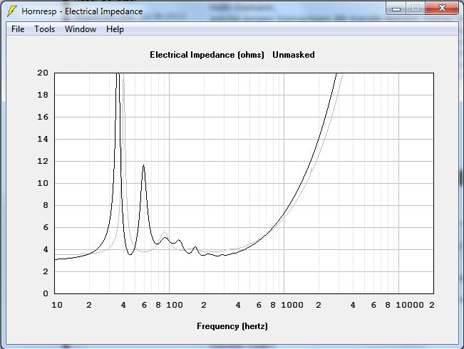
Look at this impedance measurement of a BL horn. Pick either the grey or the solid black curve (different drivers).
(not my picture)
You can exactly see the influence of the horn and the peaks. At the bottom you can see there's no horn load, above the driver fs the horn loads and the overall impedance in that area is significantly higher and there are several very good recognizable impedance peaks which correspond perfectly to the usual comb filter effect of a horn. You have the same effect if you use a compression driver and measure it without horn or a low gain WG and then introduce a higher gain horn, the electrical impedance rises with the acoustical impedance.
Now you've seen it, you can simulate it or look at it in other measurements.
And everybody knows you are just to lazy to 'look' at measurements for yourself.
Traces you provides prove that the effect is completely trivial.
I said shaking a heavy cone in the thin air is a ridiculous mis-match. Having seen the trivial effect even a horn has on the cone's behaviour, I think we can all agree it is a ridiculous mis-match that can't be fixed much by the usual fantasy of attaching a horn.
Ben
I said shaking a heavy cone in the thin air is a ridiculous mis-match. Having seen the trivial effect even a horn has on the cone's behaviour, I think we can all agree it is a ridiculous mis-match that can't be fixed much by the usual fantasy of attaching a horn.
Ben
Last edited:
I don't mean to be so hard on horns - I lived with a Klipsch bass horn for nearly 50 years. They just aren't a practicel or substantially effective means of interfacing Rice-Kellogg drivers to thin air except for upper frequencies and/or being unwieldy in size (but beautiful).
The evidence of their operation shows up in speaker efficiency, I'd say. Efficiency of a raw Rice-Kellogg driver is horrible, like one percent. A horn can raise that to a few percent. Or others may have better knowledge than I have of typical real-world efficiency.
I'd like to see measurements of a horn effecting driver Q. That would be interesting. Previous post traces (which are barely visible on my screen and not sure if the second peak disappeared???) suggests the effect is very small.
Ben
Last edited:
Just because you are not able to see or to grasp it, it must be wrong?
Look at this impedance measurement of a BL horn. Pick either the grey or the solid black curve (different drivers).
(not my picture)
You can exactly see the influence of the horn and the peaks. At the bottom you can see there's no horn load, above the driver fs the horn loads and the overall impedance in that area is significantly higher and there are several very good recognizable impedance peaks which correspond perfectly to the usual comb filter effect of a horn. You have the same effect if you use a compression driver and measure it without horn or a low gain WG and then introduce a higher gain horn, the electrical impedance rises with the acoustical impedance.
Now you've seen it, you can simulate it or look at it in other measurements.
And everybody knows you are just to lazy to 'look' at measurements for yourself.
What you see here are resonances mainly, nothing to do with acoustic impedance per se.
What you see here are resonances mainly, nothing to do with acoustic impedance per se.
Look at the impedance curve. The lowest point is where the horn doesn't load, bass ofcourse but the most important thing is to observe above the fs, the usual lowest point above the fs isn't at 60-120Hz at all, where it is at almost all bass chassis, it's at 300-400Hz. The rise of the electrical impedance in the area where the horn loads is the direct cause of the increased acoustical impedance. You can observe that behaviour at all horns. It is hower more difficult to see with horns or WG with low gain.
The rise of electrical impedance results from inductance of the voice coil.
This is a separate phenomenon from the effect of back EMF on electrical impedance. If the cone can move freely, more back EMF is generated, and impedance rises, compared to the situation where the cone is more restrained. This happens when there are resonances. Look at the large peaks in the impedance graph, these are the points where there is a lot of cone movement in relation to the voltage supplied to the voice coil.
Now, the more constrained the voice coil movements are, the lower the impedance graph goes (because less back EMF is generated). Since a horn is an acoustic impedance transformer, the effect is to constrain cone (and thus voice coil) movements. In other words, in the area where the horn is effective, or loads, impedance goes DOWN.
So, don't confound the rise of impedance (because of inductance) with the loading effect of the horn (which is to lower impedance). However, at higher frequencies, the latter effect is small compared to the effect of inductance. The reason is that cone movements are small to begin with, so the delta in back EMF only provides a small contribution to the overall impedance and it is impossible to separate out the two effects with just one measurement.
The rise of electrical impedance results from inductance of the voice coil.
This is a separate phenomenon from the effect of back EMF on electrical impedance. If the cone can move freely, more back EMF is generated, and impedance rises, compared to the situation where the cone is more restrained. This happens when there are resonances. Look at the large peaks in the impedance graph, these are the points where there is a lot of cone movement in relation to the voltage supplied to the voice coil.
Now, the more constrained the voice coil movements are, the lower the impedance graph goes (because less back EMF is generated). Since a horn is an acoustic impedance transformer, the effect is to constrain cone (and thus voice coil) movements. In other words, in the area where the horn is effective, or loads, impedance goes DOWN.
I wasn't talking about the peaks. But you are wrong anyway, compare the impedance graph of a driver in a horn and free air or with a sealed enclosure. It's impedance in a horn is everywhere above it, at least where the horn loads and at no point at all lower.
So, don't confound the rise of impedance (because of inductance) with the loading effect of the horn (which is to lower impedance).
See above (and in the former replies aswell), I was not talking about the peaks. But to prove your point, please tell me which horn got a lower impedance than the driver itself that's not caused by the crossover?
However, at higher frequencies, the latter effect is small compared to the effect of inductance. The reason is that cone movements are small to begin with, so the delta in back EMF only provides a small contribution to the overall impedance and it is impossible to separate out the two effects with just one measurement.
That's not an argument against the impedance gain, it's an argument FOR the gain.
I am curious about your experiences testing and using these drivers. High(er) Q drivers are often characterized as underdamped, while low(er) Q drivers are characterized as overdamped (all, of course, depends on the box they are used in). Thus, SS amps are claimed to increase the damping of high Q drivers, while tube amps (which often have a higher output impedance) are claimed to balance or lessen the damping of low Q drivers.
Have you found a preference of what style of amp to use with low and high Q drivers?
Retsel
sorry for the late reply, moved and been rebuilding the laboratory
Waiting on paint to dry.
I should have typed measured instead of testing. I have picked up a few tube and solid state consoles, organs and 60's-70's musical instrument speakers.
I remove the amps and speakers and run the speakers through woofer tester 2.
Then sell them.
The consoles and organs were all open back except for a GE that had a 2x2x2 box with a 5 inch driver, most of the musical equipment has been open back guitar cabs or ported bass boxes.
I have not built any audio speakers out of the older drivers as they require a box bigger then I want to build.
Now that subs are popular I guess I could try to squeeze one in a smaller box
vs open back. While working on a single 15 cabinet I modeled some Eminence alphas but I didn't want a refrigerator for a bass rig but as a monitor they would get down to 60hz.
- Status
- This old topic is closed. If you want to reopen this topic, contact a moderator using the "Report Post" button.
- Home
- Loudspeakers
- Full Range
- Why do high-Q drivers exist?