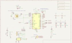
Have created 3 DSP constructions with PCBs and all, based on other older schematic/pcb tool, which worked right out of the box.
Now turned to KiCad, for which I have made a working ADAU1452, but now the latest small ADAU1701 did not work at all, and for sure can't figure out why!
I have not been able to write any program from SigmaStudio to the board. It returns right away with error.
I'm using the Wondom ICP3 as a programmer. It gives 3.3V signal out. Was firstly afraid that removing the 3V3 zeners on the programming lines that I have used before was the reason, and the chip was burned!
One mistake has been that the voltage out of the TPS5430DDA was less than the stated 3.3V and more like 3.0V. When connecting the programmer the DSP chip got warmer!!
I have corrected this on the second board I have gotten from JLCPCB before connecting. But the problem still remains.
Clock is running as it should.
What have I done wrong I wonder?
I'm planning to make an updated version, with the following changes, but I'm a bit afraid I have overlooked something obvious and it simply will not work again. I have no reason to believe the pcb is wrong. Running all design rule checks etc. and KiCad is a solid tool .....
Any insights would be appreciated before I do a new spin 🙂🙏
Now turned to KiCad, for which I have made a working ADAU1452, but now the latest small ADAU1701 did not work at all, and for sure can't figure out why!
I have not been able to write any program from SigmaStudio to the board. It returns right away with error.
I'm using the Wondom ICP3 as a programmer. It gives 3.3V signal out. Was firstly afraid that removing the 3V3 zeners on the programming lines that I have used before was the reason, and the chip was burned!
One mistake has been that the voltage out of the TPS5430DDA was less than the stated 3.3V and more like 3.0V. When connecting the programmer the DSP chip got warmer!!
I have corrected this on the second board I have gotten from JLCPCB before connecting. But the problem still remains.
Clock is running as it should.
What have I done wrong I wonder?
I'm planning to make an updated version, with the following changes, but I'm a bit afraid I have overlooked something obvious and it simply will not work again. I have no reason to believe the pcb is wrong. Running all design rule checks etc. and KiCad is a solid tool .....
- Will replace the TPS5430DDA with a AMS1117-3.3, as the TPS5430DDA is overkill for this small build, and I'll have 3V3 right out of the box
- The muting circuit will not work as is .... way to simple. Need something like a TVL809
- XL7015E1 decal not correct ... it should be TO252-5 NOT TO-263-5
Any insights would be appreciated before I do a new spin 🙂🙏
Attachments

Can you talk to ADAU1452 over I2C bus at all? Can you talk to the EEPROM over I2C bus? Do you have a scope?
What is the error message you get when you try to program ADAU1452? Does it just say ERROR? Do you see any I2C bus activity with a scope?
What is the error message you get when you try to program ADAU1452? Does it just say ERROR? Do you see any I2C bus activity with a scope?
Hi Mark
Sorry for late answer ..... too busy with work :|
It's my ADAU1701 board that does not work.
I get an error when connecting to the ADAU1701 with SigmaStudio 4.4 using Link Compile Download. See attached.
I have tried to just read or write the EEPROM See attachment 2 and 3.
See also E2Prom Setting. It's an AT24C256C. Have set the com speed down to 50kHz ... should not really matter (same result with 10khz and 100khz)
Yes on the scope there is clear communication ... data sent from ISP3 to DSP board
Attachments


Ok, I blindly admit to failure .... I must have hit my head ..... I have turned the programming connector the wrong way around!!!!😱😵😢 Damn ... Damn, Damn 🤣
So I have had +5V directly in on WP .... must have burned both DSP and EEPROM in the process ....
Switching the connector other way around did not work .....
Ok, at least it now makes sense 🙂
I'll do a new PCB with a few learnings and improvements and ship it off for production .... Stay Tunes 😉
At least I did not burn the ICP3 🙂 .... still working ..
At some point I actually have fried the ICP3, so have updated to a ICP5 works really well, and does not get as hot as the ICP3.
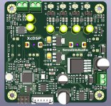
To avoid pop and noise when starting up and even more when shutting down, I implemented 2 x MAX9892ELT+T and MAX809L to short the output. I have tried in a few ways, and this is also not the first PCB where I have tried these, but I can't get it to work and there is just a massive pop at shot down!
So now I have given up on this path. I have only had good experience with using PCM5102A as DAC as it uses TI's DirectPath technology which creates a negative voltage on the chip to create a balanced supply for the output. It also contains enough circuit to make it work well at start and shut down, with only a minimum pop (there is something but is't low enough to be ok).
It also means you can skip an output cap on all outputs, so yes it takes up more real estate on the pcb, but it also saves some.
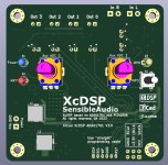
So I made e new PCB with PCM1808, 2 x PCM5102A and the ADAU1701.
This get it up to same level better than the MiniDSP HD, with regards to THD, with the PCM1808/PCM5102A combination promising -93db THD+N. .... and the PCM5102A are really quite cheap for the performance.
Also changed the connection to the PCM1808 so it now runs in master mode.
With the 2 PCM5102As there is a bit less GPIOs, which is of course a down side, so now I have one switch, 2 LEDs and 2 potentiometers.
On the last PCB the switch was a push button, where the new implementation it is a small rocker switch.
Before I was planning to use a LED to show the "position", but now with one LED less I now have a physical "read out" - on/off.
I think the switch can be useful for e.g. changing setup on a subwoofer from music to movie, or for changing setting and response on a main speaker, either when developing to find out what sounds best or to switch between upper roll off settings.
Kept the PCB size to 6x7 cm.
Anyway received the PCB and assembled today, and it all seems to work as it should 🙂 ..... but well we are also at version 4!! 😉
To avoid pop and noise when starting up and even more when shutting down, I implemented 2 x MAX9892ELT+T and MAX809L to short the output. I have tried in a few ways, and this is also not the first PCB where I have tried these, but I can't get it to work and there is just a massive pop at shot down!
So now I have given up on this path. I have only had good experience with using PCM5102A as DAC as it uses TI's DirectPath technology which creates a negative voltage on the chip to create a balanced supply for the output. It also contains enough circuit to make it work well at start and shut down, with only a minimum pop (there is something but is't low enough to be ok).
It also means you can skip an output cap on all outputs, so yes it takes up more real estate on the pcb, but it also saves some.
So I made e new PCB with PCM1808, 2 x PCM5102A and the ADAU1701.
This get it up to same level better than the MiniDSP HD, with regards to THD, with the PCM1808/PCM5102A combination promising -93db THD+N. .... and the PCM5102A are really quite cheap for the performance.
Also changed the connection to the PCM1808 so it now runs in master mode.
With the 2 PCM5102As there is a bit less GPIOs, which is of course a down side, so now I have one switch, 2 LEDs and 2 potentiometers.
On the last PCB the switch was a push button, where the new implementation it is a small rocker switch.
Before I was planning to use a LED to show the "position", but now with one LED less I now have a physical "read out" - on/off.
I think the switch can be useful for e.g. changing setup on a subwoofer from music to movie, or for changing setting and response on a main speaker, either when developing to find out what sounds best or to switch between upper roll off settings.
Kept the PCB size to 6x7 cm.
Anyway received the PCB and assembled today, and it all seems to work as it should 🙂 ..... but well we are also at version 4!! 😉
Attachments


Have not really considered ..... need to test some more .... maybe I'll just post the gerbers/production files
- Home
- Source & Line
- Digital Line Level
- Why didn't it work ... ADAU1701 small build