That's a good hint but not bulletproof. For instance, JRC never specifies polarity of bias current and they make amplifiers of both polarities without bias cancellation. The relation between input bias and voltage noise (too good to be likely) or input bias and current noise (too bad to be plausible) is a better indicator IMO. One has to watch out for superbeta inputs, though.
In other news, the mystery of phase reversal protection has been resolved, and not in a happy way.
This chip HAS phase reversal.
It only occurs within a few hundred millivolts of the negative rail, but it's there. Try it yourself - set unity gain with 10k feedback resistor and short the input to VEE - the output will jump towards VCC. It happens for the same reason as in TL072, RC4558, NJM-about-anything and similar circuits - the noninverting input acts as an emitter follower and drags the whole input stage so low that there is no way to feed current into the VAS.
And it gets worse. One thing the datasheet didn't tell you is that the input stage is protected from excessive differential voltage by clamping diodes, like in NE5532 and many others. Replace the feedback resistor with a dead short and something may very likely blow up, or if the input clamp keeps up with the 50mA short circuit output current, the chip may slowly cook itself if it happens on both channels at maximum supply voltage. I haven't tried.
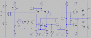
And now the schematic. It's simplified to avoid clutter, but all important bits are included.
- I omitted some resistors, for example in series with Q6 emitter and the input clamping diodes
- there may or may not be resistors in series with Q11 base and C2, my magnification is not sufficient to see for sure
- some resistors are used as "jumpers" to allow traces to cross, I haven't included them if they don't seem to play any other role
- all current sources are EF-enhanced mirrors, akin to Q3-Q5
- D13 and D14 are actually the input to the mirror which generates I3-I6
- currents I7-I9 are generated separately and decrease with temperature, likely to stabilize the output bias
In other news, the mystery of phase reversal protection has been resolved, and not in a happy way.
This chip HAS phase reversal.
It only occurs within a few hundred millivolts of the negative rail, but it's there. Try it yourself - set unity gain with 10k feedback resistor and short the input to VEE - the output will jump towards VCC. It happens for the same reason as in TL072, RC4558, NJM-about-anything and similar circuits - the noninverting input acts as an emitter follower and drags the whole input stage so low that there is no way to feed current into the VAS.
And it gets worse. One thing the datasheet didn't tell you is that the input stage is protected from excessive differential voltage by clamping diodes, like in NE5532 and many others. Replace the feedback resistor with a dead short and something may very likely blow up, or if the input clamp keeps up with the 50mA short circuit output current, the chip may slowly cook itself if it happens on both channels at maximum supply voltage. I haven't tried.
And now the schematic. It's simplified to avoid clutter, but all important bits are included.
- I omitted some resistors, for example in series with Q6 emitter and the input clamping diodes
- there may or may not be resistors in series with Q11 base and C2, my magnification is not sufficient to see for sure
- some resistors are used as "jumpers" to allow traces to cross, I haven't included them if they don't seem to play any other role
- all current sources are EF-enhanced mirrors, akin to Q3-Q5
- D13 and D14 are actually the input to the mirror which generates I3-I6
- currents I7-I9 are generated separately and decrease with temperature, likely to stabilize the output bias
Attachments
- Status
- This old topic is closed. If you want to reopen this topic, contact a moderator using the "Report Post" button.