mikeks said:
This is incredibly untrue...i am sorry...really..
A closed-loop power amp. cannot have a change in group delay of 50ns between 1khz and 5khz....
I thought we are talking about "reasoning" not "believing"...
These numbers are taken from sims of an amp with limited openloopbandwidth: (closedloop)
1khz: 0.1708° -> 474.4ns
5khz: 1.2350° -> 686.1ns
Difference: 211.7ns
(Values doublechecked)
Ooops, you are right, this is not 50ns !
Now gonna check if this has audible effect...
MikeB
MikeB said:1khz: 0.1708° -> 474.4ns
5khz: 1.2350° -> 686.1ns
Difference: 211.7ns
(Values doublechecked)
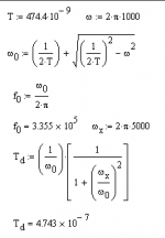
Here's what I came up with for a single-pole circuit. A group delay of 474.4 ns at 1 kHz corresponds to a -3 dB frequency of 335.5 kHz. Sounds good. Plugging that back in to the group delay formula shows that the group delay should be 474.3 ns at 5 kHz.
The group delay should be maximum at DC, going to zero as the frequency becomes large.
Attachments
Andy_c, Mikeb
I have run some simple sims and have seen group delays like you have posted. I haven't taken it much further, haven't had the time. Now for the stupid questions...
The sims I've done has been for a simple discrete circuit. I am assuming that the sim is actually best case since I haven't put anything in for trace C, etc.
Wouldn't a fast opamp have a better group delay than a discrete circuit since everything is matched and on the same die? I am of course thinking line level not power level. I'm not at the math level you guys are. Or am I missing something completely?
Is this group delay, or change in group delay vs freq seeable on a THD test? I wasn't quite sure after a couple posts I read. I assumed that with the notch filter on a meter that it wouldn't see a 1/2 degree shift.
Hi !
Actually, i have absolutely no idea if the change in groupdelay has
anything to say or what causes it. (Should be the feedback itself,
trying to compensate phasehifts)
I did my small program applying dynamic phaseshift to a wavefile,
none of the phaseshifts had audible effect. Even the wildest shifts
(+/-90° in 500hz interval) were not audible. So the human ear is
absolutly insensitive to this kind of phaseshift, the only phaseshift
interpreted by the brain seems to be for stereoimaging, but these
shifts are more like >100us.
Maxdelay for eardist of 20cm would be (using 334m/s sonicspeed) ~598uS.
To MikeGergen, it was my idea that these phaseshifts are invisible
with any kind of thd, as they don't generate harmonics. Maybe that
is the reason why it's not audible.
Okay, i continue with my small program, now simulating globalfeedback
on a wavefile. The first results were promising, i got glare sound just
like an amp with wrong adjusted feedback. It's really annoying, listening
to these waves gave me headache within a few minutes...
To mikeks & andyc, the values are from a closedloop-amp.
Increasing openloopbandwidth does not reduce this effect, it get's
sligthly larger... I can check other topologys, maybe i checked with
really bad circuits ?
Mike
andy_c said:Just to clarify, I'm not in the "harmonic distortion describes everything you need to know about distortion" camp, unless the nonlinearity being considered is memroyless.
I am yet to be convinced that 'other' forms of distortion do not generate harmonics that by definition can be detected by simple THD+N....

viz:
mikeks said:
I am curious: Is everyone satisfied that:
1)..that NFB is an inherently bad thing?
2)...that 2-tone stimuli provide insight into circuit behaviour that THD analysis cannot?
3)...and that moreover, THD will not detect changes in linearity (or non-linearity thereof) that may be detected by the multi-tone
approach?
Thanks for the explanation Mikeb. I didn't think that these phase shifts would be audible. I got confused with all the postings, I wasn't able to pull out of it what I needed to.
Myself, I haven't spent a lot of time dealing with distortions, phase shifts, etc. at this level. I have spent much time looking at the layout of the amp instead. I have found that layout, components, cleanliness of the circuit, ground plane Z, has a bigger impact for me. I'm not saying that the work you've done is pointless, on the contrary, it has been educational.
From another thread going on, my favorite books are Printed Circuit Handbook by Clyde Coombs and Low Level Signal Measurement by Keithley Instruments. These books have helped me deal with noise and distortion more than many of the equations that have been posted. I have wondered if the real world, i.e. board layout, supply bypassing, etc. doesn't completely swamp out many of the advantages of trying to get a "perfect' distortion free amp and mess up the design goals to some degree.
Again, thanks and keep up the good work.
Mike
mikeks said:
I am yet to be convinced that 'other' forms of distortion do not generate harmonics that by definition can be detected by simple THD+N....
Well, "describes everything you need to know about..." and "can be detected by.." are two different things. I worked for years on narrowband receivers having sharp bandpass filters. The third harmonic of the receiver center frequency might be, say, 80 dB down from the center frequency value because of the filter. It seems obvious that harmonic distortion measurements are absolutely useless for this type of circuit.
Check out the Czerwinski article that jcx is referring to. For more details, email me.
andy_c said:..............I worked for years on narrowband receivers having sharp bandpass filters. The third harmonic of the receiver center frequency might be, say, 80 dB down from the center frequency value because of the filter. It seems obvious that harmonic distortion measurements are absolutely useless for this type of circuit.
I was thinking audio frequency really......Audio precision kit will measure that level quite straightfowardly...
Folks, something is wrong. Either the dynamic phase shift manifests itself as a separate entity, or Barrie Gilbert is barking up a tree. After all, most amps, and IC's can measure down to -100dB or below under reasonable conditions.
Almost all professional audio test equipment can measure to -100dB, and some can measure below this by 20-40dB. You should ask Bruno to confirm your predictions. He has the equipment to do it.
Almost all professional audio test equipment can measure to -100dB, and some can measure below this by 20-40dB. You should ask Bruno to confirm your predictions. He has the equipment to do it.
The third harmonic of the receiver center frequency might be, say, 80 dB down from the center frequency value because of the filter. It seems obvious that harmonic distortion measurements are absolutely useless for this type of circuit.
Yes indeed, and that is the general consensus in distortion analysis in RF courses today where the IP3 point is used almost exclusively.
I am yet to be convinced that 'other' forms of distortion do not generate harmonics that by definition can be detected by simple THD+N....
For the conditions where THD is valid - me neither. But it is almost entirely of academic interest.
/Magnus
And the human ear is VERY sensitive to phaseshifts,
So the human ear is absolutly insensitive to this kind of phaseshift, the only phaseshift interpreted by the brain seems to be for stereoimaging, but these shifts are more like >100us.
So, MikeB - what is your current standpoint on phaseshifts?

For those who want more insight into the human hearing system I can recommend the "bible" for med. instrumentation "Medical Physics and Biomedical Engineering" by B.H. Brown et al, ISBN 0-7503-0368-9 with the chapters on audiology and physics of the senses.
/M
john curl said:Folks, something is wrong. Either the dynamic phase shift manifests itself as a separate entity, or Barrie Gilbert is barking up a tree.
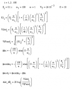
John, the third harmonic is part of Gilbert's calculations. I quote:
"The third-harmonic distortion is the ratio of the second term in (15) to the vector sum of the sine and cosine fundamentals in (17). Since we have chosen to work 'backwards' from input to output, this is the distortion referred to VIN. For moderate levels, though, the percentage is very similar whichever way round the calculation is made"
Then he goes on to compute the third-harmonic distortion at 2V, 4V and 5V output. I've just generalized this to do it all the way from 0.1V to 10V. I've attached a capture of the MathCad worksheet used to compute this, which I checked against his results for the levels he computed. 'E' in his notation becomes 'Ei' in my notation, because the subscripting is used for arrays in MathCad (E = 0.1, 0.2,...10.0). Gilbert is in no way, shape or form making any claim that the variable phase shift with level is somehow independent of the third-harmonic distortion term. To see this, you just have to go through the math in detail.
Attachments
Is the distortion, with or without negative feedback applied? I seriously doubt that you can get .5% distortion or so, AM distortion from a single frequency with today's audio grade op amp. Isn't Barrie showing the open loop distortion rather than the closed loop distortion?
It's the closed-loop distortion wiith a closed-loop gain of 10 at a frequency of 1/100 the gain-bandwidth product. I used this because these were the same conditions Gilbert used, so it allowed me to check my answers against his for the levels he used.
For a 797, this would correspond to a frequency of 1 MHz.
Also, this assumes "weakly nonlinear" behavior. To work backwards from output to input with the tanh() function, he had to approximate the inverse hyperbolic tangent function as atanh(x) = x + x3 / 3.
This makes the third-order distortion proportional to amplitude squared, but this only holds for the weakly nonlinear region. That is, we'd need all terms in the atanh() power series for it to give correct results for very large signals.
And Gilbert's own words on TIM:
"Predictably, Otala's 'discovery' only added welcome fuel to the fire of those who were quite convinced that these new-fangled transistor amplifiers were genetically incapable of pleasing the audiophile ear, a notion which, like all myths, persists unabated, in spite of the fact that the root cause of TIM is now completely understood, and can easily be avoided in transistor amplifiers expressly designed for the most demanding audio applications.
"Predictably, Otala's 'discovery' only added welcome fuel to the fire of those who were quite convinced that these new-fangled transistor amplifiers were genetically incapable of pleasing the audiophile ear, a notion which, like all myths, persists unabated, in spite of the fact that the root cause of TIM is now completely understood, and can easily be avoided in transistor amplifiers expressly designed for the most demanding audio applications.
Swedish Chef, Barrie Gilbert wrote that AFTER 25 years of first learning about Otala's 'discovery' I would hope that you too will learn what is really happening 25 years from now, or even sooner. ;-)
Barrie is a very competitive guy, and he thought that I was crazy when I discussed TIM with him in Feb 1974. He didn't give me any real input at the time, except that he had no idea what I was talking about. Now it is easy and obvious.
This is typical of academic types.
They tend to only give begrudging credit to others. In this latest paper, he didn't even footnote Matti's paper on PIM given almost 20 years earlier. Still, better late than never.
A small footnote: Barrie Gilbert holds an 'honorary doctorate' by Oregon State University, but Matti Otala earned his PhD on his own and has been a professor. To refer to him as 'Mister Otala' in this paper is an implied insult.
OK, I'm still following this. If I'm reading correctly;
Mikeb, you're saying that small phase shifts of under a few degrees are not detectable or audible. John C, you're saying they are audible. Now I'm really confused, but my wife will tell you that anyways(ok ok, a bad shot at humor)
I've always been under the impression that a TIM test would detect this type of distortion and not a THD test for the reasons listed about the notch filters. Ok, I'm an idiot, what am I missing?
Mike Gergen said:OK, I'm still following this. If I'm reading correctly;
Mikeb, you're saying that small phase shifts of under a few degrees are not detectable or audible. John C, you're saying they are audible. Now I'm really confused, but my wife will tell you that anyways(ok ok, a bad shot at humor)
I've always been under the impression that a TIM test would detect this type of distortion and not a THD test for the reasons listed about the notch filters. Ok, I'm an idiot, what am I missing?
There are several different conversations going on, so it does get confusing. Regarding phase shift, John and I have been discussing the Gilbert paper, in which Gilbert looks at the TIM problem (let's call it the "input stage distortion problem"). Gilbert looks at if from a different perspective than the much earlier Otala papers. That is, with a single sine wave input, what does the input-output phase shift look like at a single frequency? Gilbert showed that when an amplifier has a distorting input stage, the iniput-output phase shift at a single frequency is dependent on signal level. This doesn't happen with linear circuits, and is clearly undesirable. John was concerned that the same mechanism that causes the level-dependent phase shift (namely input stage distortion) might introduce so little conventional harmonic distortion that it would be in practice undetectable. Since Gilbert's analysis also treats harmonic distortion as a by-product (but only the third harmonic), I went back and computed the harmonic distortion vs output signal level as well as the phase shift vs output signal level using Gilbert's equations. It turns out that when the input stage distortion occurs to the extent that the input-output phase lag is one degree more than its value when it is behaving purely linearly, the third harmonic is about 0.5 percent of the fundamental.
Audibility is of course a completely separate issue.
- Status
- This old topic is closed. If you want to reopen this topic, contact a moderator using the "Report Post" button.
- Home
- Amplifiers
- Solid State
- "What's your reasoning?" and not "What's your belief?".