Thank you for your answear.
I just need some precisions on what you said:
when you say, moving the port up and down and seeing of it changes the FR. By the FR, do you mean the bass extention (how low it goes, the shape of the rolloff) or only the harmonic ripples?
And what about moving the driver up/down?
I haven't tryed to play with the port position now, but yesterday I tryed various positions for the driver (0 to 20 inches from the top, with 1 inch step) and compared the curves.
The best one was at 7 inches. By the best one, I mean the one with the smaller ripples. The simulations were done with 0.001 stuffing.
Warning! Newbie weighing in!
I've been lurking the past couple of months, and I figure it's time to jump in!
Thanks everyone, MJK in particular - I understand about enough of waves to start to follow your derivation - your work on this and sharing it is fantastic. I'm about to start my own first ML-TL this next week using Vifa TC18 woofers, and I think I'm now starting to understand ML-TL's thanks to everyone here.
Bricolo:
It does look like you've got a TL, but I think you need to change your port tuning or lengthen your enclosure. You've got an increase in SPL at abt. 50 Hz followed by a very sharp drop. Lengthen your port and increase the height of your cab to 46 and see what happens...
Now you're starting to get that rolloff that Bob Brines mentioned. (Thanks, BTW, Bob, I've been using your -3dB @ 40Hz you list on your site as my design target!)
As for the difference between a BR and a TL... let me give my own take. Now, I've never built one, so I'm kind of putting this out as much as a question as a statement! In a BR, you're tuning to a 3-D box mode. There will be all kinds of higher frequency harmonics of different internal modes off of walls etc. Different port placements & stuffing will give different amounts of these harmonics, whose frequencies will be all over the place. Hard to model...
In a TL, you've lengthened the box so that you now excite "pipe resonances", along the single long dimension. These give extra 1/4 wave resonances at 3/4, 5/4, etc, which normally should be avoided - they're pretty high amplitude. But these higher resonances can be damped by selective stuffing, leaving a much cleaner port output.
At least, that's what I think today!
I've been lurking the past couple of months, and I figure it's time to jump in!
Thanks everyone, MJK in particular - I understand about enough of waves to start to follow your derivation - your work on this and sharing it is fantastic. I'm about to start my own first ML-TL this next week using Vifa TC18 woofers, and I think I'm now starting to understand ML-TL's thanks to everyone here.
Bricolo:
It does look like you've got a TL, but I think you need to change your port tuning or lengthen your enclosure. You've got an increase in SPL at abt. 50 Hz followed by a very sharp drop. Lengthen your port and increase the height of your cab to 46 and see what happens...
An externally hosted image should be here but it was not working when we last tested it.
Now you're starting to get that rolloff that Bob Brines mentioned. (Thanks, BTW, Bob, I've been using your -3dB @ 40Hz you list on your site as my design target!)
As for the difference between a BR and a TL... let me give my own take. Now, I've never built one, so I'm kind of putting this out as much as a question as a statement! In a BR, you're tuning to a 3-D box mode. There will be all kinds of higher frequency harmonics of different internal modes off of walls etc. Different port placements & stuffing will give different amounts of these harmonics, whose frequencies will be all over the place. Hard to model...
In a TL, you've lengthened the box so that you now excite "pipe resonances", along the single long dimension. These give extra 1/4 wave resonances at 3/4, 5/4, etc, which normally should be avoided - they're pretty high amplitude. But these higher resonances can be damped by selective stuffing, leaving a much cleaner port output.
At least, that's what I think today!
Ok, I followed the tread with interest and I learned a lot so far. One thing I cant understand: The Fostex recommended enclosure (35L-blue) has a big bump. The other one I simulated to get it as flat as possible. I wonder why they recommended that way. It's much more attractive to use 25L box than 35L box. What am I missing?
Great discussion!
Thanks
/Greg
Great discussion!
Thanks
/Greg
Attachments
The other way is to add 1.5Ohms (red line) in ser with the speaker and decrease the sensitivity by 1dB, use the same box and tune the port frequency and I get a nice curve that goes much lower than recommended. Or maybe they know that most people will use it with a tube amp and have high output impedance (1-2 ohms) and that why they suggested the enclosure the way they did, but the port dimentions ar wrong that way too.
What would you do? Would you use a resistor?
/Greg
What would you do? Would you use a resistor?
/Greg
Attachments
OK, this post addresses Bricolo's plots. Very interesting results, I have never done this type of series of simulations before so I have not completely proved out an answer. But a few things jump out at me as I look at the shape of the plots.
Lets start by looking at the extremes, the port at 20 inches and at 40 inches. Every ripple in the plots represents a standing wave along the length of the enclosure. Looking at these two plots you can see two different behaviors for the second standing wave at about 170 Hz.
For the 20 inch plot the SPL response rolls off and then dives to a null at about 170 hz before rebounding. My guess is that if we could see the plot of the woofer and terminus there would be a sharp null in the terminus response and the driver response. Looking at the top half of the enclosure a quarter wave standing wave is possible.
f = c / 4 x L = 344 / 4 x (0.5 m) = 168 Hz
If this standing wave existed, it would see two paths to follow at the mid heigth of the enclosure. Either out throught the port or down to the bottom of the enclosure. The acoustic impedance for the path down to the bottom of the enclosure is zero so all of the standing wave will be sucked towards the bottom of the enclosure. Nothing will exit the port. A half wavelength standing wave will exist with a zero pressure at the mid point of the enclosure. My guess is that this enclosure design is a BR, the only way I would know for sure is to plot the pressure in the enclosure at the tuning frequency.
Now lets look at the other extreme where the port is at 40 inches. The resonance at 170 Hz has a completely different shape. There is a slight rise followed by a deep dip before bouncing back. In the plot of the woofer and terminus the terminus probably has a peak at this frequency. The rise, then dip, then bounce back is created by the terminus peak changing phase (almost 180 degree phase shift) as it goes through resonance. The next peak at aout 320 Hz shows the mirror image of this resonance as this peak in the terminus response goes through a second almost 180 degree phase shift. My guess that this enclosure design is an ML TL but again the only way to tell for sure is to plot the pressure along the length of the enclosure.
If I am correct and we can determine if the enclosure is a BR or a ML TL by the shape of this first peak, then we should be able to look at the plots in between these two extremes and find the transition.
Port at 20, 22, 24, 26, and 28 inches = BR
Port at 30 = transition point
Port at 32, 34, 36, 38, 39, and 40 inches = ML TL
That would be my guess at interpreting the data, I may be completely off base since I have never looked at this topic in any great detail. I am sure that there will be additional detailed questions, I may not have much more to add since I am way out at the extreme of my own understanding.
Hope that helps,
Hi GregGC,
The Fostex design with the big hump at resonance is probably an attempt to beat the baffle step problem by producing a greatly exaggerated (spelling?) bass. I bet that design sounds terrible with booming one note base.
The flat design you plotted looks nice but my guess is that the program treats the speaker as if it were working in 2 pi space over the entire frequency range. That is also what my MathCad worksheets assume. So if you built that design, the bass would sound weak. If you go the the phase plug thread, going on now, you will see some of this discussed along with some explanation on how I treat the baffle step in Fostex and Lowther ported enclosures.
There is also a short write up on designing BSC circuits on my site under the Genrral Speaker Related Articles heading. This document shows how to size a BSC and how to adjust it to get the best performance.
Hope that helps,
MJK said:Hi GregGC,
The Fostex design with the big hump at resonance is probably an attempt to beat the baffle step problem by producing a greatly exaggerated (spelling?) bass. I bet that design sounds terrible with booming one note base.
The flat design you plotted looks nice but my guess is that the program treats the speaker as if it were working in 2 pi space over the entire frequency range. That is also what my MathCad worksheets assume. So if you built that design, the bass would sound weak. If you go the the phase plug thread, going on now, you will see some of this discussed along with some explanation on how I treat the baffle step in Fostex and Lowther ported enclosures.
There is also a short write up on designing BSC circuits on my site under the Genrral Speaker Related Articles heading. This document shows how to size a BSC and how to adjust it to get the best performance.
Hope that helps,
Thanks a lot! I'll keep reading.
/Greg
We're getting closer and closer
Thank you Martin. Your explanations are very usefull.
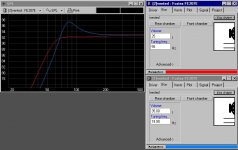
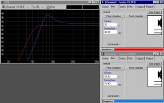
Since I'm not sure about what you call the "plot of the woofer and terminus", I'll attach the whole results for the 20in and 40in simulations.
But how can I plot the pressure along the length of the enclosure I'm not sure it's a graph on the worksheet.
Here are the results for the port at 20 in
Thank you Martin. Your explanations are very usefull.
Since I'm not sure about what you call the "plot of the woofer and terminus", I'll attach the whole results for the 20in and 40in simulations.
But how can I plot the pressure along the length of the enclosure
I'm not sure it's a graph on the worksheet.Here are the results for the port at 20 in
Attachments
The woofer and terminus plotted right below the system response. The title on each plot tells you all that you need to determine which one to look at.
These MathCad worksheets do not plot pressure as a function of length. That requires a different method, either an ANSYS FEM model or a different MathCad worksheet I have someplace on my hard drive that I wrote years ago.
These MathCad worksheets do not plot pressure as a function of length. That requires a different method, either an ANSYS FEM model or a different MathCad worksheet I have someplace on my hard drive that I wrote years ago.
Since Bricolo did simulation of port placement between 20 to 40 inches, which one of these are considered optimised ? One of the difficulties confronting rookies like myself is that I can run the simulation and look at the graph without knowing and undertanding what to look for.
Hi Kleung,
My guess is that after adding some stuffing to the enclosures, that all of Bricolo's simulations would look almost identical. So from a calculation perspective, they would all perform the same. I think that any small differences in performance are in the small details of construction.
I personally like to have the port at the far bottom end of the enclosure and the driver near the top. This puts the port near the floor to help get some bass reinforcement and also creates a long path from the driver through stuffing to kill any midrange leakage.
If the enclosure works as a quarter wavelength tuned pipe, then the high pressure points in the box are very local and the fundumantal only produces high pressure at the top near the driver. The top is the strongest place in the cabinet. I feel that this is the fundamental different from a standard bass reflex design where the entire cabinet is pressurized. I have found that the ML TL enclosure does not require a lot of bracing and is fairly dead when made out of a high quality plywood.
The simulations will not tell you any of those things. So once you have a design simulation that looks good on paper, sketch an enclosure and look at the other details in the design.
Hope that helps,
I'm not sure that stuffing will make them all look the same.
Especially not the ones with the port from 30 to 20 inches. Look how the 50-150Hz is, this won't be changed with stuffing.
Are you sure they can be all called "optimised"? You said it yourself, some are ML-TLs, some are BRs, some are inbetween
Especially not the ones with the port from 30 to 20 inches. Look how the 50-150Hz is, this won't be changed with stuffing.
Are you sure they can be all called "optimised"?
You said it yourself, some are ML-TLs, some are BRs, some are inbetweenMLTQWT-BR difference?
Hi!
What is the sonic difference in the reality between a MLTQWT and a classic Bassreflex design? I mean: I modeled this two kind of design with the same driver and I got a 100% identical reasult with the same box volumen. The frequency plot was the typical BR kind and the groupdelay was very bad for both too.
I ask this because I am looking for a laudspeaker design with nice transient response and deep-controlled bass. Should it be a classic TL design?
Thanks!
Tyimo
I guess what gets missed in these discussions is why one would build a ML-TL in the first place. (Disregard tht TQWT -- pointed at the top and big at the bottom with the driver ~half way down the pipe. These are never appropriate for large drivers.)
The difference between a ML-TL and a BR is nature of the resonant mechanism. A ML-TL is a quarter wave resonator, a BR is a helmholtz resonator. The real problem is that a designer will go into a box simulator, UniBox, WinIDS, whatever, and get a volume and a port size. Then, he draws up a tall, thin floor-stander. Upon testing, he finds a bunch of unexpected spikes in the FR curve, possibly also in the impedance curve, and the box is tuned way too low.
The box simulators presume a cubic box. Once the box gets stretched out significantly, quarter wave modes set in and the simulation fails. MJK's worksheets, however, handle the problem. As far as the equations go, there is no difference between a BR and a ML-TL.
If you use the same volume for a cube and a tall, thin box, you will get the same cut-off frequency and slope, assuming that the port size is adjusted for the ML-TL. Given the same cut-off and slope, the group delay will be the same. You don't have to use a QB3 alignment. You can use an EBS alignment. At the cost of doubling the box volume, you can drive the cut-off almost an octave lower. With a lower cut-off, you at least delay the onset of high group delay, hopfully low enough to not be a problem.
Bob
Disregard tht TQWT -- pointed at the top and big at the bottom with the driver ~half way down the pipe. These are never appropriate for large drivers.
For low value Le or FR drivers I agree, but 'pointed' top pipes are a good way to get additional gain from typical sub, bass, and midbass drivers.
GM
hello!
I had try to use round, square, rectangular, exponential port, egg-glass port. got boomy. don't like it.
now I'm use marble cube cabinet 30L, 10" driver, 100W FET amp (+-32V), 75mm diam 25 cm length port, aperiodic membrane and have not problem also
form of box, damping material - have not differense. this is sub - 25-80Hz. 2 pcs 12 db/oct active filtres. enough.
you're welcome
Hi Bob!
Thanks a lot for your answer! I think since long time it is the most important answer in this theme. So, a ML-TL sounds like a BR...., but I would like to get the nice classic TL sound :-((
Could you suggest me a TL design with I could reach ca.30Hz on F3? ( I have a good 18 cm driver with Fs: 25Hz, Qts: 0,395.)
Is there any possibility to calculate the real frequency slope with the room gain in the MJK's Mathcad open ended TL sheet?
Thanks!
Does somebody know Gabriel Karlsson' TL-KV program? It is very easy to use, but I don't know it's reasult is correct or not?
Tyimo
- Status
- This old topic is closed. If you want to reopen this topic, contact a moderator using the "Report Post" button.
- Home
- Loudspeakers
- Multi-Way
- What's the difference between a TL, a ML-TL and a TQWT?