The other tube amp, where I used a DC servo/bias setting, was a totem pole amp.
What I did was making a normal adjustable negative grid voltage to the lower tube.
Then I had a two transistor comperator where one input was the out put from the amp (the other was tied to ground) and the output from the comperator adjusted bias on the upper tube.
What I did was making a normal adjustable negative grid voltage to the lower tube.
Then I had a two transistor comperator where one input was the out put from the amp (the other was tied to ground) and the output from the comperator adjusted bias on the upper tube.
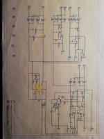
Here is the schematic of the part of the powerrsupply, where the bias servo is.
R14 is the biassetting for the lower tube and the two transistors Q1 and Q2 form the comperator that adjusts the upper tube, so there always is 0 V DC at the output.
Hope this can help a little.
R14 is the biassetting for the lower tube and the two transistors Q1 and Q2 form the comperator that adjusts the upper tube, so there always is 0 V DC at the output.
Hope this can help a little.
Attachments
I used the same input as the Atmasphere amps. Look at post #25 in this thread.
Ralph was kind enough to show it to all of us Diy-ers.
I use a driver tube for each 6C33 though.
I have studied and replicated Ralphs differential cascode with 6SN7. My worry is that the lower tube is not the best choice since 6SN7's load lines don't look very linear at those small voltage levels. Could an ECC88 be much linear for the lower tube?
Can anyone help me on this?
The bottom tube should have about 90 volts across it. We get pretty good linearity with that. Regarding 6C33s as a power tube, a separate driver tube seems to be the best way to go with that. That is how we set up our Novacron amplifier.
If using 6C33s, the socket is prone to failure. Its a good idea to use magnet wire for the filament connections, as this helps move heat away from the contacts and the insulation is less likely to melt.
If using 6C33s, the socket is prone to failure. Its a good idea to use magnet wire for the filament connections, as this helps move heat away from the contacts and the insulation is less likely to melt.
Hi Ralph, great work with the Novacron. I saw some pictures of the amp online and fell in love instantly.
Thanks to your incredibly beautiful work I have decided to start playing with vacuum tubes.
One year later I have built this baby. I won't share pictures of the build just yet because it's all over the desk with hook up wires going back and forth.
What's your tail CCS chosen value? I like to run it at 16mA so I can abuse the 6SN7s incredible linearity at 8mA per side.
Attachments
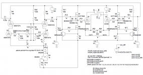
^^ I think you can eliminate R1 and R7- that will improve the CMRR.
I think also that the performance can be improved by using a zener diode in place of R8 giving the same voltage. However, some zeners can be noisy so you might have to install a PI network to feed the grids of the top tubes of the voltage amplifier.
It appears that J1 is being used as compensation for the DN2540. IME a 2-stage CCS with two MOSFETs in series gives better performance with improved CMRR of the voltage amplifier as a result. The DN2540 is a good choice but should have diode protection on its gate; We usually run this part as the bottom part of the two stage CCS with an IRF820 on top. The resulting circuit looks a lot like its tube counterpart that I posted in the M-60 schematic way back when on this thread.
^^
The resulting circuit looks a lot like its tube counterpart that I posted in the M-60 schematic way back when on this thread.
The tube counterpart sounds amazing by the way

The tube cascode CCS has more dinamics? A fet + depletion mosfet ccs has more resistance (impedance) than a tube one. I am trying to understand why some things sound better but measure the same or worst.
LE: Or it has to do with linearity of the CCS... I think we all agree that for now there's nothing more linear then a triode
LE: Or it has to do with linearity of the CCS... I think we all agree that for now there's nothing more linear then a triode
Last edited:
^^ High impedance and linearity are both important. A good solid state CCS is a bit trickier to execute as well. If you do it right, the solid state CCS will have about an order of magnitude greater performance but if you don't do it right in a word it will suck.
For some reason, most of the solid state circuits I see online in amplifier circuits are terrible. I have to assume the designers don't realize that performance is being left on the table.
For some reason, most of the solid state circuits I see online in amplifier circuits are terrible. I have to assume the designers don't realize that performance is being left on the table.
Hi, I am building atmasphere M60, I have a lot of 6080 GE tubes, can I used them instead of 6AS7 or is better to order some Russian 6N13S?
Alex
I use the Russian version. Ralph recommends them over the 6080.
He also recommends applying filament voltage to them for 24 hours (I think) to
cure the cathode. Reduces the risk of flash over.
This is a long thread but all the info you need is in it.
Hi, I am building atmasphere M60, I have a lot of 6080 GE tubes, can I used them instead of 6AS7 or is better to order some Russian 6N13S?
Alex
Hello friend, 6AS7G in truth it is much better because it has a heat sink on top of its structure, attached to the G1, this allows the stage in class A2 or AB2 to work, which generates grid current and nor 6080 neither 6AS7GA do not have.
The 6080 can be problematic. Some are actually 6AS7As which have the small grid heatsink. GEs are a good example of this and it doesn't seem to matter if they have a W or WA suffix.
OTOH there are 6080s that have the same grid heatsink that you see in American 6AS7Gs. We have some branded 'Beckman' that are like this and they are simply marked '6080'. This kind of 6080 works out a whole lot better, but they must be preconditioned (filament only, no B+) for at least 4 days and 4 nights. The preconditioning stops when B+ is applied- its important to be patient!
The 5 ohm 5 watt cathode resistor is recommended. If a 1 ohm 5 watt is used if the tube arcs it will be destroyed immediately.
Hi Ralph, Thanks for helping,
I have two GE 6080 versions, both look to have the small grid heatsink, so I'll better use the russian 6N13S
I am planning to use your schematic that's why I asked for cathode resistors
I have one more question, B+(2) should be regulated? and B-(2) LC filtered? or just an RC filter is fine?
I have two GE 6080 versions, both look to have the small grid heatsink, so I'll better use the russian 6N13S
I am planning to use your schematic that's why I asked for cathode resistors
I have one more question, B+(2) should be regulated? and B-(2) LC filtered? or just an RC filter is fine?
- Home
- Amplifiers
- Tubes / Valves
- What tubes for a OTL tube amp?