Hi,
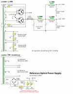
Was wondering if someone was able to confirm my thoughts. The attached schematic specifies the 'cerafine' duel capacitor.
Lets take the 47uf + 47uf - I presume that this could be replaced with two 47uf caps in parallel or say one 100uf cap. Is this correct?
Also, the second cap on the power supply which is unspecified is presumably a 47uf + 47uf?
Thanks for the help with this simple problem.
Cheers,
Rob
Rob11966 said:Does the hybrid valve/diode rectification make a difference compared with valve only?
No.
Rob11966 said:I thought that the first capacitor after a GZ34 ad to be less than 50uf!
If you are using one rectifier tube yes*, but the schematic uses two, so you can scale the capacitor values accordingly.
Sheldon
*You can exceed the recommended value if you increase the series resistance according the the formula shown on some of the data sheets
Uh, the schematic shows two seperate 47uF caps, one on each side of a choke. So I would take this to mean that each is 47uF. But I could be wrong...
So in this case "47uF + 47uF" may not mean 100uF, it means two 47uF caps... they could be a 2-section single can, or two seperate caps.
Also, this schematic uses paralleled GZ34's, so 47uF or 2x 47uF should be OK as far as repetitive peak current goes... but this is also dependent on the transformer resistance.
Pete
pmillett said:Uh, the schematic shows two seperate 47uF caps, one on each side of a choke. So I would take this to mean that each is 47uF. But I could be wrong...
So in this case "47uF + 47uF" may not mean 100uF, it means two 47uF caps... they could be a 2-section single can, or two seperate caps.
Also, this schematic uses paralleled GZ34's, so 47uF or 2x 47uF should be OK as far as repetitive peak current goes... but this is also dependent on the transformer resistance.
Pete
In the pics on Ciufolli's site, it looks like a total of four electrolytic caps, with three leads each, so I infer from that, that each cap on the schematic is represents a full dual cap.
Sheldon
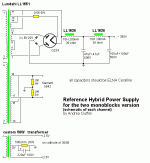
Rob11966 said:With respect to the 2 GZ34's that makes sense ut Ciuffoli also has a monoblock power supply with a similar capacitor arrangement but in this case there is a choke just before the first capacitor. Do you have any thoughts on this?
Keep in mind that I don't have near the experience of many of our contributors. With that caveat:
If the choke meets the requirement of critical inductance, you can pretty much put any reasonable amount of capacitance behind it.
Going forward, I highly recommend playing around with PSUD. It's free. It's easy. And, if you plug in accurate values for your transformer, it's very accurate. You can quickly try many PS variations and begin to develop your informed intuition by looking at the graphic outputs. Pete mentioned the repetitive peak current, as the limiting factor for the rectifier. You can easily simulate that value with PSUD, and make sure you are safely within limits.
Sheldon
Hi again Sheldon,
I have been modeling with PSU but I have come unstuck with it.
With respect to the stereo power supply I can't model the duel GZ34's with this programme - this power supply seems too complex for the programme. Furthermore the programme only seems to allow me to model a center tapped transformer.
With respect to the monoblock power supply, the Lundahl 1651 has a 500v secondary which makes no sense to me when looking at the final voltage of 390v. When I model this on PSU, I get a final RMS voltage of close to 600v. I am presuming this has something to do with the fact that my PSU model uses a center tap but I may be way off target with this explanation.
Thanks for your patience. Please excuse my ignorance with this I am moving from the 'copying' phase of my building to the 'just understanding' phase. In fact I can now pick up Morgan Jones and understand a fair bit.
Cheers,
Rob
Yes, PSUD does limit your configurations, but you can work around it by scaling it. Just double the transformer resistance, double the choke resistances, half the capacitance, and half the current load of your supply. The repetitive rectifier current value, will be the same as for each of the paralleled rectifiers in your full design.
Or, if you want to approximate a hybrid bridge, just model tube, then ss, and the values halfway between will be close.
If you highlight the transformer/diode/rectifier block, and right click, you will get a *change* dialog box. From that you can select tube or ss, bridge, or rectifier.
I get around 425V if I model that supply. That's pretty close. His line voltage may be a little lower. Make sure you are loading the supply with the expected operating current. I usually like to use a current source instead of a resistor load. You can model step functions with that and look for any evidence of ringing.
Sheldon
Sheldon said:
In the pics on Ciufolli's site, it looks like a total of four electrolytic caps, with three leads each, so I infer from that, that each cap on the schematic is represents a full dual cap.
Sheldon
At first that's what I thought too. But (at least on the 300B PSE amp) there's also another 47uF (half of a dual) used in each of the channels (on the amp schematic). Also, from what I could make out in the photos, it didn't look like all the caps were paralleled.
Pete
pmillett said:
At first that's what I thought too. But (at least on the 300B PSE amp) there's also another 47uF (half of a dual) used in each of the channels (on the amp schematic). Also, from what I could make out in the photos, it didn't look like all the caps were paralleled.
Pete
I think you are right.
Sheldon
The way I read the schematic, if these 47uF+47uF caps are dual can caps, then one half of a dual 47uF cap is one one side of the first 4H choke, and the other half of the cap (the other 47uF) is on the other side of the choke. For the 100uF+100uF cap, one half is after the 10H choke on the right channel, the other half is after the other 10H choke in the left channel. In other words, you are using a total of one 47uF+47uF cap and one 100uF+100uF cap.
Chris
Chris
chrish said:The way I read the schematic, if these 47uF+47uF caps are dual can caps, then one half of a dual 47uF cap is one one side of the first 4H choke, and the other half of the cap (the other 47uF) is on the other side of the choke. For the 100uF+100uF cap, one half is after the 10H choke on the right channel, the other half is after the other 10H choke in the left channel. In other words, you are using a total of one 47uF+47uF cap and one 100uF+100uF cap.
Chris
The schematic is ambiguous, but if you count up the caps in the pictures on Andrea's site, and compare to the schematic, it jives with Pete's analysis - two dual 47's and two dual 100's, total.
Sheldon
Hi Chris,
I can see your point and it makes sense - in fact enough sense to worry me!
I do however think that Sheldon is correct based on -
1. The photo's of the caps on the website and
2. The fact that the monoblock power supply specifies a 47uf + 47uf and a 100uf + 100uf on the schematic (posted above) which is clearly for one channel only.
What do you think?
Rob
PS I would love to hear from someone who has actually built this thing!
Rob11966 said:
I can see your point and it makes sense - in fact enough sense to worry me!
I do however think that Sheldon is correct based on -
Don't worry Rob, build. As indicated before, you are well withing safe limits even with 2X 47U right after the paralleled rectifiers. Certainly safe with one, and I'd guess PS hum will be minimal.
Sheldon
- Status
- This old topic is closed. If you want to reopen this topic, contact a moderator using the "Report Post" button.
- Home
- Amplifiers
- Tubes / Valves
- What to replace these caps with?

