Yes should be possible, the pentode would act like a triode seen from the connection points (grid, cathode and plate).
And as (almost) always, someone has done it, see:
GroupBuild Forum - 300B SE Project, Part 9 - E180F, E280F, D3a pentodes - triode connected - Damir, March 09, 2006 at 14:19:29
And as (almost) always, someone has done it, see:
GroupBuild Forum - 300B SE Project, Part 9 - E180F, E280F, D3a pentodes - triode connected - Damir, March 09, 2006 at 14:19:29
Kopfhoerer-Amp_C3g, von Oliver Stick
Err, see post #10
The name would be me then...
")
And as (almost) always, someone has done it, see: ....
but may not autiomaticly mean its good
anyway, I happen to have that schematic, although with the C3g, but avoided it because of the reasons mentioned ... but maybe it is ok

I wonder if its the same way with chokes and pentodes ?
Attachments

but may not autiomaticly mean its good
No thats right, but it was meant as an idea for further experiments. When you use a pentode , triode connected it behaves as one (well, almost), Rp would be more like that of a triode, and then could be threated as one, and the use of a ccs should be possible, technically. If it would sound good and perform well, is another question.
I wonder if its the same way with chokes and pentodes ?
Choke loading a pentode could be a good idea, as it self act as a ccs, ccs loading would be a conflict, but using an inductor would be a possible way to do it. But because the internal resistance, in pentode mode, is rather high, the inductance needed would be of a large value.
In triode mode, a lower value should be needed.
Would be an interesting experiment, though.
Last edited:

I played around a little
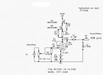
this is the test schematic
supply 300v
CCS 17mA

I connected a 10k resistor as load
this is a 10kHz sinus triangle and square wave, the only difference you can see is on the triangle, the output is a little rounded on the top on that one
1v in 50v out on the sinus wave
I have adjusted the oscilloscope to match the waves so ignore the amplitude on the scope.
input signal is at the bottom on all three waves
The next thing to do is to measure distortion, this is just a visual exploration with a signal generator

this is the test schematic
supply 300v
CCS 17mA
I connected a 10k resistor as load
this is a 10kHz sinus triangle and square wave, the only difference you can see is on the triangle, the output is a little rounded on the top on that one
1v in 50v out on the sinus wave
I have adjusted the oscilloscope to match the waves so ignore the amplitude on the scope.
input signal is at the bottom on all three waves
The next thing to do is to measure distortion, this is just a visual exploration with a signal generator
I tried Led bias with a red led now and it looks promising, glows red and fancy
And my distortion meter seems to measure a bit higher distortion than I expected from C3g, its around 1% dist at 50v output.
But It might be my ferrograph rts2 wanking out
How does one measure distortion easy today? with a soundcard perhaps?
And my distortion meter seems to measure a bit higher distortion than I expected from C3g, its around 1% dist at 50v output.
But It might be my ferrograph rts2 wanking out
How does one measure distortion easy today? with a soundcard perhaps?
And my distortion meter seems to measure a bit higher distortion than I expected from C3g, its around 1% dist at 50v output.
Try to increase the 10 KOhm load resistor to 100 K.
Thorsten
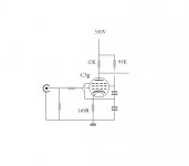
I tried Led bias with a red led
In your schematic the bias about 3V (17mA, 180R).
Try two red LED (1.7..1.8V between 10..20mA) series.
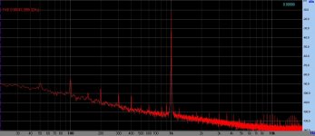
C3g preamp/driver (anode load 11mA CCS, cathode:235R // 100uF) at moderate (1V RMS) input voltage produce 0.1-0.5% THD.
Hmmm
So I connected and measured a couple of times, hauled up my HP 332A dist meter to have as a reference to my ferrograph and after a tune up they measure almost the same, about 0,4% dist @ 300v B+ 1Khz 1v input and with 240 Ohm CR
I found a pink led that measured 3,05v but the distortion rose to 0,5% with the pink led bias
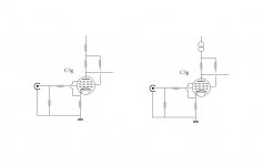
CCS @ 17mA on both
I will measure a CCa and a D3a just to have something to refer to
So I connected and measured a couple of times, hauled up my HP 332A dist meter to have as a reference to my ferrograph and after a tune up they measure almost the same, about 0,4% dist @ 300v B+ 1Khz 1v input and with 240 Ohm CR
I found a pink led that measured 3,05v but the distortion rose to 0,5% with the pink led bias
CCS @ 17mA on both
I will measure a CCa and a D3a just to have something to refer to
0.1-0.5% THD estimation based on (about) three dozen -used- C3g measuring.
The best specimens I used in the C3g phono (C3g, 18mA CCS anode load, green LED bias, passive RIAA, C3g, 18mA CCS anode load, green LED bias, D3a cathode follower -9mA CCS as cathode load-).
C3g, C3g, D3a phono at 30mV input:
The best specimens I used in the C3g phono (C3g, 18mA CCS anode load, green LED bias, passive RIAA, C3g, 18mA CCS anode load, green LED bias, D3a cathode follower -9mA CCS as cathode load-).
C3g, C3g, D3a phono at 30mV input:
Attachments
Last edited:
- Home
- Amplifiers
- Tubes / Valves
- What to do with C3g tubes