Would 2-3A be sufficient for this amplifier? I found a deal on a linear Lab PSU, it's 13,8v 2-3A. With my Maxim Class D, I got a good improvement in bass control and dynamics by going from a wall wart 15v 3A SMPS to a laptop brick 12v 5A SMPS, but am willing to give the linear PSU a try.
That'll work well. The amplifier is limited to 2A, but since it uses a heatsink perhaps it uses a bit more that's dissipated as heat. It's not explicit whether it's 2A overall or output. Keeping it at a good temperature will keep power up.
This amp does more power based on voltage, so long as it has the proper current for its limit. But as I've been saying, mouser or Chinese will define how high you want to go. 87db speakers in a small room are fine if you can run 18v. But for less, and go be ideal, one would have a bit more efficient speakers.
Reverse polarity protection isn't very valuable unless you predict you'll make the most obvious mistake possible. 1uf caps will extend bass. The stock caps might have bass in lower region, but they're harder to drive so you'll lose some. 1uf corner frequency is below 10hz, so it's pretty easy. I might bump it up even a touch more in capacitance. What sucks is that you don't know if you got 25k or 35k input impedance.
These are the easiest little amps to get someone going on DIY, so I love them for getting people to try something. Something that has a reward of very good sound for that matter.
Picked up the LPS tonight, can't go wrong for 10 euros. It only had the screw caps for the +/- terminals missing.
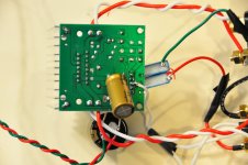
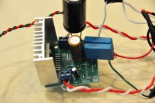
It's a major improvement, I hear more depth in soundstage, warmth in the mids and the top-end is more defined. There is a heightened sense of realism, and at the same time it is easier to listen to.
Pic: https://onedrive.live.com/?id=2A8394C1DA053C64%212808&cid=2A8394C1DA053C64&group=0&parId=root&parCid=2a8394c1da053c64&authkey=%21ALSv7MZ41ytedx8&o=OneUp
I use the DC socket and checked polarity with a DMM, steady 13.77v . My input caps are 1uf Vishays MKT. I played with monster Film/Oil caps on my TA2024, but I'd rather not go that route again.
This has been a lot of fun.
Last edited:
Post pictures and we can check if you made any mistakes. Also let us know what power supply you're using.
Lots of people have done the mods without any problems.
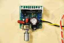
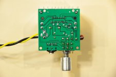
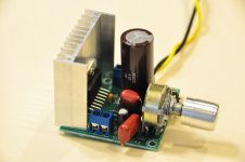
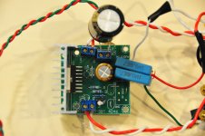
Pics attached, three pics each for build #3 and #4. First one has fancy DACT 50k stepped attenuator in place of no-name pot that came with the board. Diode replaced with a jumper wire, bigger power cap, polypropylene input caps. #4 follows your build guide v2 to the letter.
As was suggested above, the "shotgun" approach of doing all the mods in one go is probably unwise... but in all my other dabblings I've managed to pull this kind of work off without any issue. Not that I'm particularly experienced, but these tda7297 amps and the mods are really quite simple. <shrug>
Power supply is this: Parts Express Power Supply Regulated 3-12 VDC 2A 6-Way Part #120-536. Set to 12V. Obviously not the last word in power supplies, but it's what I have on hand. I have a nice Sigma11 PSU I built, but killed it with my first attempt at this tda7297 when I connected the polarity backwards. (Will get around to fixing it one of these days...)
Attachments
The + and - are incorrectly labeled on the left side (away from DC power in). Pin 1 and 15 are +. You have one speaker out of phase.
I just noticed a big error on their part. Don't connect SG at the designated spot. Run it directly to pin 8 (if the board is upside down, on the bottom row, count in to the 4th pin). Both SG's need to be twisted around R and L until the separate at the capacitors. The reason is that PG's current is running directly though the connection for SG. This will greatly improve the quality of the amplifier. Please do these things and check back. I'll modify my guide to correct their problem. Apologies I didn't notice this before, as the datasheet has a similar PCB board layout that doesn't exhibit this problem.
I do hope it's not your power supply that's cooked, rather than the amplifier, or the amp was damaged... They're cheap, but shipping is slow.
Last edited:
87db speakers in a small room are fine if you can run 18v. But for less, and go be ideal, one would have a bit more efficient speakers....
One advantage over Tripath is that The TDA7297 does not sound too harsh when driven hard.
...you don't know if you got 25k or 35k input impedance.
I am not sure I understand this, I will have to read up on input impedance
These are the easiest little amps to get someone going on DIY, so I love them for getting people to try something. Something that has a reward of very good sound for that matter.
This is it. I have actually been going through the TDA datasheet to figure out how it works. Now I want to learn more about circuits.
Next step is to box it up with a Stepped attenuator.
The + and - are incorrectly labeled on the left side (away from DC power in). Pin 1 and 15 are +. You have one speaker out of phase.
I should have mentioned that I noticed that right away. Even with the distortion, the "hollow" sound of having a speaker out of phase is obvious!
I just noticed a big error on their part. Don't connect SG at the designated spot. Run it directly to pin 8 (if the board is upside down, on the bottom row, count in to the 4th pin). Both SG's need to be twisted around R and L until the separate at the capacitors. The reason is that PG's current is running directly though the connection for SG. This will greatly improve the quality of the amplifier. Please do these things and check back. I'll modify my guide to correct their problem. Apologies I didn't notice this before, as the datasheet has a similar PCB board layout that doesn't exhibit this problem.
SG = signal ground, and PG = power ground, right? That seems quite straightforward. Thanks for the help!
I do hope it's not your power supply that's cooked, rather than the amplifier, or the amp was damaged... They're cheap, but shipping is slow.
The Parts Express power supply I linked above is fine. But with build #1 I definitely did something to my Sigma11 PSU, as it was built for 12V output, now it reads 4.something. Amp builds #1 and #2 went in the trash. Looks like #3 and #4 might be savable. The last two came from a 5-pack, so I'm still sitting on three spares.
")
Actually, the 5-pack I bought I thought would come as bare PCBs and a bag of parts. But actually each one came finished. I actually wanted the kit/bag of parts format, as it would have saved me some work. I'm also sitting on a tda7297 chip I bought from Mouser or DigiKey... waiting until I have something working respectably before I put it at risk.
How's the progress of the listening tour?
Or:
SG = Safety Ground/Protective Earth
If PE = power ground
is that AC Power Ground
or
DC supply common?
Should not signal common and DC supply common be almost the same thing?
All abbreviations and TLAs (Three Letter Acronyms) are confusing.
The word 'ground' in it's self is confusing.
SG = Safety Ground/Protective Earth
If PE = power ground
is that AC Power Ground
or
DC supply common?
Should not signal common and DC supply common be almost the same thing?
All abbreviations and TLAs (Three Letter Acronyms) are confusing.
The word 'ground' in it's self is confusing.
I use SG=signal ground, and PG= power ground for in chassis designation.
And yes, ground, return., etc etc, very annoying. It's a mistake that was never seen coming from back in the day.
The SG needs to connect at the chip to avoid power currents. It's a flaw of that PCB. SG has to be connected to PG or the amp won't turn on, on these chips. It allows a lot of error, or poor sound for a TV.
Without bypassing to the chip SG pin, all power current flows right through between the mini Jack and pot vias (holes), and that's the path to SG pin as well.
Pics attached, three pics each for build #3 and #4. First one has fancy DACT 50k stepped attenuator in place of no-name pot that came with the board. Diode replaced with a jumper wire, bigger power cap, polypropylene input caps. #4 follows your build guide v2 to the letter.
As was suggested above, the "shotgun" approach of doing all the mods in one go is probably unwise... but in all my other dabblings I've managed to pull this kind of work off without any issue. Not that I'm particularly experienced, but these tda7297 amps and the mods are really quite simple. <shrug>
Power supply is this: Parts Express Power Supply Regulated 3-12 VDC 2A 6-Way Part #120-536. Set to 12V. Obviously not the last word in power supplies, but it's what I have on hand. I have a nice Sigma11 PSU I built, but killed it with my first attempt at this tda7297 when I connected the polarity backwards. (Will get around to fixing it one of these days...)
Which one sound better?
Neither, yet. They both exhibit the blatant distortion. I haven't had a chance to try Destroyer OS's suggestions yet. I'm actually more interested in his fancy tda7297 implementation - hoping the listening tour comes to me soon.Which one sound better?
But if I get a chance to work on those two cheapies, I'll report back with my impressions.
Neither, yet. They both exhibit the blatant distortion. I haven't had a chance to try Destroyer OS's suggestions yet. I'm actually more interested in his fancy tda7297 implementation - hoping the listening tour comes to me soon.
But if I get a chance to work on those two cheapies, I'll report back with my impressions.
Unfortunately my funding approach with a crowd didn't come close to completion. However, you'll still get to have a listen
 and some PCB's will be available.
I just noticed a big error on their part. Don't connect SG at the designated spot. Run it directly to pin 8 (if the board is upside down, on the bottom row, count in to the 4th pin). Both SG's need to be twisted around R and L until the separate at the capacitors. The reason is that PG's current is running directly though the connection for SG. This will greatly improve the quality of the amplifier. Please do these things and check back. I'll modify my guide to correct their problem. Apologies I didn't notice this before, as the datasheet has a similar PCB board layout that doesn't exhibit this problem.
I just need to check as I am about to P2P one of these. Are you saying that nothing connects to pin 9, which shold be the SG according to the ST schematic?
OK, that's what I thought.
And finally where should the PW ground and SG ground be joined?
They're already joined on the board. The point is to reduce noise by avoiding current on the input ground line, SG.
If they are not connected the amplifier will not turn on.
They're already joined on the board. The point is to reduce noise by avoiding current on the input ground line, SG.
If they are not connected the amplifier will not turn on.
Except I am doing point to point. Join pin 8 to 9 directly I guess.
Except I am doing point to point. Join pin 8 to 9 directly I guess.
If you're wiring a point to point TDA7297 chip...
I prefer to run a PG connection to connect on the wire headed to the SG pin from the SG input, but I connect the PG wire before the capacitors.
Yes I know it sounds weird, but the amplifier sounds better this way.
If you want to buy a PCB from me I have a few right now. PM me if you like. (free BC337 with board)

Last edited:
Here's the demo amp in a review. *Sorry the name says Salis, it is actually Folsom
Vapor Audio Perfect Storm Speaker Review - Home Theater Forum and Systems - HomeTheaterShack.com
Vapor Audio Perfect Storm Speaker Review - Home Theater Forum and Systems - HomeTheaterShack.com
- Home
- Amplifiers
- Chip Amps
- What the heck? It's less than lunch!