I don't think they are. I will study this aspect. On this board signal ground connects to ground plane near the chip's pin.
Regarding the bypass caps, I took the footprint of wima fkp1 I think, and smallest voltage is at 400VDC I think. Initially I designed it for me as I have those caps laying around")
I will make a smaller footprint and also add a connection for smaller electrolytics.
Regarding the bypass caps, I took the footprint of wima fkp1 I think, and smallest voltage is at 400VDC I think. Initially I designed it for me as I have those caps laying around
I will make a smaller footprint and also add a connection for smaller electrolytics.
Nope, I've used wima mkp10/63v. Those have 10mm pin spacing. Can you recommend a good pin spacing for bypass capacitors? I could go for 7.5mm and I guess the electrolytic ones have 2.5mm to 3mm, so I could add another solder pad inside the footprint for smaller electrolytic capacitors.
Simple solution for the spacing: Just provide multiple vias to fit either 400v box caps or 63v (normal size) box caps at all four places you've got polyester caps. That will get the needs covered plenty well.
When adding the vias, I suggest to arrange so that when normal size 63v box caps are installed, then the cables aren't obscured. That would be elegant.
Edit: The normal size for 63v box cap is 5mm (including red wima, vishay and avx T*). The 400v cap that I have on hand is 10mm.
When adding the vias, I suggest to arrange so that when normal size 63v box caps are installed, then the cables aren't obscured. That would be elegant.
Edit: The normal size for 63v box cap is 5mm (including red wima, vishay and avx T*). The 400v cap that I have on hand is 10mm.
Last edited:
I bought 2 tda7297; 1 mod by changing supply cap to panny FA 4700/25v and the other using BG 4700/16v cap and fed by a simple 9v unregulated CL supply... when the input sig is paused, volume turn to max; panny mod can hear a faint low freq hum while the BG mod is totally silent... looks like better supply cap does remove power supply noise quite effectively...
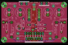
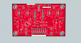
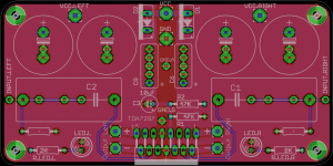
I found some time to make the necessary adjustments. I put pads for 2.5mm, 5mm, 7.5mm and 10mm. Also the positive connection for polarized capacitors is the lower pad so you mount the capacitors closer to the chip rather than power supply. All the extra holes are ground. With this setup you could install an electrolytic capacitor of 2.5mm/5mm pin distance with 10mm maximum diameter. Or 2.5mm/5mm/7.5mm/10mm pin distance non-polarized capacitors.
*edit:
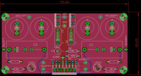
any way I could remove the silkscreen for the diodes? I'd like to leave only the pads and put a diode symbol with the mounting direction. I can't seem to figure it out. I also tried editing and deleting the diode design but that didn't work either.
*edit:
any way I could remove the silkscreen for the diodes? I'd like to leave only the pads and put a diode symbol with the mounting direction. I can't seem to figure it out. I also tried editing and deleting the diode design but that didn't work either.
Attachments
Last edited:
I just realised that the input capacitors are very small. I want to add a larger footprint so larger (physically) capacitors can be mounted. I'm looking at Wima PP caps and they have a pin spacing of 27.5mm. 10 or 15mm seems way to small. Since the board house charges the same for all boards that are sub 10cmx5cm then I will make the board a bit larger to accommodate larger capacitors. Also I will put padded holes for 15/10/5mm like the bypass caps.

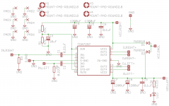
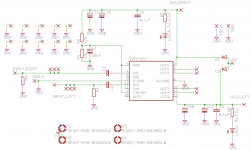
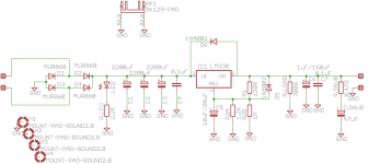
Well, the thing is that this chip has dual power rails.
If you look here: http://datasheet.octopart.com/TDA7297-STMicroelectronics-datasheet-10837159.pdf
you will see that pins 3 and 13 are both Vcc. Since this is a stereo chip it basically has one power input for each of the two amplifiers inside the package. This way you get a better separation between the channels and that results in better audio quality. You can think of it as two monoblocks, each with it's own power supply. Off-course, you can use a single power supply and add the two diodes if you don't want to install two separate power supplies.
Well, the thing is that this chip has dual power rails.
If you look here: http://datasheet.octopart.com/TDA7297-STMicroelectronics-datasheet-10837159.pdf
you will see that pins 3 and 13 are both Vcc. Since this is a stereo chip it basically has one power input for each of the two amplifiers inside the package. This way you get a better separation between the channels and that results in better audio quality. You can think of it as two monoblocks, each with it's own power supply. Off-course, you can use a single power supply and add the two diodes if you don't want to install two separate power supplies.
Thanks for the explanation. I think I'll stick to single supply for simplicity and costs.
Oh, and please keep at least on LED as I'd use it as a power-on indicator
Theoretically yes. It should sound better but that also depends on your speakers, ears etc. You can use one psu and later add the second one if you want to try it one thing to notice is that the supplies have to be the same type and output voltage. I wouldn't recommend adding a regulated psu as a second unit next to an unregulated one. I don't have experience in this matter so I wouldn't risk using two different ones.
one thing to notice is that the supplies have to be the same type and output voltage. I wouldn't recommend adding a regulated psu as a second unit next to an unregulated one. I don't have experience in this matter so I wouldn't risk using two different ones.I will make the order on Monday or Tuesday.
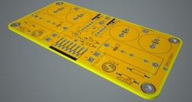
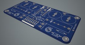
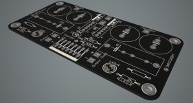
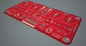
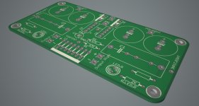
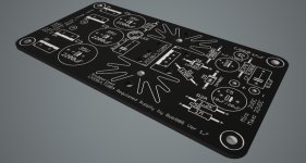
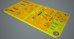
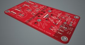
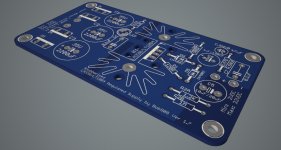
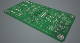
So far I've made some calculations regarding the price of the boards. To avoid large taxes I've decided to set a limit to 20 boards for the amplifier and 20 boards for the psu. A total of 40 boards. This would limit the total value to something that I won't have to pay a large amount of taxes on. I will put the prices in different color options, basically there's green which is free in the price of the board and then there are red/blue/yellow/white which costs 10$ extra per total no matter if I make 10 or 20 boards. This applies to one board type so per total color pcb will add 20$ to the total price. Black costs 20$ per pcb type and I don't know if it's worth it. I guess if we'd get like 50-100 boards then it wouldn't matter. I also added some renderings with different colors so you decide if it's worth it or not
I am still waiting for an answer from the pcb company regarding an offer of free shipping with orders over 50$ and, if so, then the price per pcb goes down but there's a month waiting time until I get them, and then there's the time you wait to receive the pcb from me.
So I will put the price with free shipping and fast shipping (from them to me). To that price you add the shipping price from me to you and paypal fees.
I mention that I'm not making anything on this, I just want to help others if they want my boards This way I get mine as well.
I just rounded the prices in my favor like this. If the price per pcb costs me 3.56$ I'm asking 3.6$.
OK, so the prices are as follows:
Free shipping:
amplifier/regulator color/green
10/10 4.2$/3$
20/10 3.6$/2.8$
20/20 3.3$/2.7$
Faster shipping (I get them in 3-5 days):
10/10 5.9$/4.7$
20/10 4.9$/4$
20/20 4.3$/3.7$
The majority rules so I will just go with the flow. You decide the colors and shipping times. Also if it seems that you're interested in a total of 18 amp boards and 11 or 12 psu boards then I will go with 20/10. If we get past half decade then we round it up. I will keep the extra boards until someone wants them, so I'm taking that risk
20 boards of each helps me pay only VAT tax on the package. So now the final price depends on how many boards are you interested in.
So far, including me, there are 8 amp boards and 7 psu boards reserved. If I'm only doing 20 boards in total you will pay me after I get the package and I've tested them. Else it's too much cash and I am not able to pay the whole order. I have paypal and I will take only that. I haven't done this before.
Also I will check the shipping prices, hope there are somewhere on the internet , and I will make a BOM for both boards from different suppliers. I am using tme.eu but will look at others. I am not that anal about parts, I will probably end up using Wima caps for input and bypass. I've added lots of pads for different pin distances so everyone should be OK.
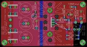
The regulator board can be used with a number of adjustable regulators. LM338/LT1083/LT1084/LT1085 etc. I guess you could use LM317 but I wouldn't bother.
Also keep in mind the voltages you are working with. You want to size the capacitors voltage rating accordingly. For output voltage calculations you can go here:
LM317 / LM338 / LM350 Voltage Regulator Calculator and Circuits
R1 needs to be about 120ohm for LM338/LT108x. I've added another resistor in parallel with R2 on the psu board so you can better dial in the voltage. I don't like a pot in that spot as it can move in time. Also there's a snubber option on the output of the board, you can use it or not. Same goes for the parallel resistor.
If you get the amp board and psu board then don't install any LEDs on the amplifier, the psu has one.
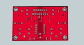
These boards are made to be cased. That's why there is no connector on them. You solder wires directly between the boards. Also you have to think of a way to cool the chip, mount it on a piece of aluminium inside the case.
Regarding the colors, I would make the psu red and the amplifier white or blue
So far I've made some calculations regarding the price of the boards. To avoid large taxes I've decided to set a limit to 20 boards for the amplifier and 20 boards for the psu. A total of 40 boards. This would limit the total value to something that I won't have to pay a large amount of taxes on. I will put the prices in different color options, basically there's green which is free in the price of the board and then there are red/blue/yellow/white which costs 10$ extra per total no matter if I make 10 or 20 boards. This applies to one board type so per total color pcb will add 20$ to the total price. Black costs 20$ per pcb type and I don't know if it's worth it. I guess if we'd get like 50-100 boards then it wouldn't matter. I also added some renderings with different colors so you decide if it's worth it or not
I am still waiting for an answer from the pcb company regarding an offer of free shipping with orders over 50$ and, if so, then the price per pcb goes down but there's a month waiting time until I get them, and then there's the time you wait to receive the pcb from me.
So I will put the price with free shipping and fast shipping (from them to me). To that price you add the shipping price from me to you and paypal fees.
I mention that I'm not making anything on this, I just want to help others if they want my boards
This way I get mine as well.I just rounded the prices in my favor like this. If the price per pcb costs me 3.56$ I'm asking 3.6$.
OK, so the prices are as follows:
Free shipping:
amplifier/regulator color/green
10/10 4.2$/3$
20/10 3.6$/2.8$
20/20 3.3$/2.7$
Faster shipping (I get them in 3-5 days):
10/10 5.9$/4.7$
20/10 4.9$/4$
20/20 4.3$/3.7$
The majority rules so I will just go with the flow. You decide the colors and shipping times. Also if it seems that you're interested in a total of 18 amp boards and 11 or 12 psu boards then I will go with 20/10. If we get past half decade then we round it up. I will keep the extra boards until someone wants them, so I'm taking that risk
20 boards of each helps me pay only VAT tax on the package. So now the final price depends on how many boards are you interested in.
So far, including me, there are 8 amp boards and 7 psu boards reserved. If I'm only doing 20 boards in total you will pay me after I get the package and I've tested them. Else it's too much cash and I am not able to pay the whole order. I have paypal and I will take only that. I haven't done this before.
Also I will check the shipping prices, hope there are somewhere on the internet
, and I will make a BOM for both boards from different suppliers. I am using tme.eu but will look at others. I am not that anal about parts, I will probably end up using Wima caps for input and bypass. I've added lots of pads for different pin distances so everyone should be OK.The regulator board can be used with a number of adjustable regulators. LM338/LT1083/LT1084/LT1085 etc. I guess you could use LM317 but I wouldn't bother.
Also keep in mind the voltages you are working with. You want to size the capacitors voltage rating accordingly. For output voltage calculations you can go here:
LM317 / LM338 / LM350 Voltage Regulator Calculator and Circuits
R1 needs to be about 120ohm for LM338/LT108x. I've added another resistor in parallel with R2 on the psu board so you can better dial in the voltage. I don't like a pot in that spot as it can move in time. Also there's a snubber option on the output of the board, you can use it or not. Same goes for the parallel resistor.
If you get the amp board and psu board then don't install any LEDs on the amplifier, the psu has one.
These boards are made to be cased. That's why there is no connector on them. You solder wires directly between the boards. Also you have to think of a way to cool the chip, mount it on a piece of aluminium inside the case.
Regarding the colors, I would make the psu red and the amplifier white or blue
Attachments

Last edited:
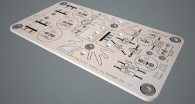
This is the regulator board.
I will look over the boards tomorrow to see if I've done any mistake.
Another mention, I've added another GND pad on the amplifier board near the main GND connection. I would like to test something when I get the board. It seems that the Power Ground and Signal Ground are internally connected and I have to connect them on board. I've read that a good practice is to connect both pins to GND in different places so you separate the digital side from the analog one and I'm planning on trying to not put the Signal Ground leg on the pcb but connect it directly via wire near the main ground connection. I will test it and see if it matters. Should be easy to do.
Also I'm wondering, if I will use two PSU boards then will I need two GND connections as well on the pcb? Maybe someone with more knowledge could chime in.
Another mention, there's one mounting hole connected to ground on each PCB. If you don't need to earth the board with the case then put some isolation between the screw and the pad.
Attachments
Last edited:
Is this correct?
You require money up front from group members to buy boards of your own design with an untested circuit which you will then send on to them if the boards prove to work?
Why not develop the boards on your $ and then organize a group order if they prove to be superior to the stock finished and shipped versions?
I personally love the stock $6 amp and have gone back to it again after a few days with tpa3116.
Well for 20 boards I will buy them then get the cash after I check them.
I'm not forcing anyone nor do I make anything off this. If there's something wrong with the design then anyone is free to say something.
More than that, if the boards prove to not be ok then I will refund the cash to everyone... It's not like I'm going to compromise myself for a few tens of $ I've been on this forum for a couple of years now and I've received great help from members here.
I'm not forcing anyone nor do I make anything off this. If there's something wrong with the design then anyone is free to say something.
More than that, if the boards prove to not be ok then I will refund the cash to everyone... It's not like I'm going to compromise myself for a few tens of $
I've been on this forum for a couple of years now and I've received great help from members here.- Home
- Amplifiers
- Chip Amps
- What the heck? It's less than lunch!