Schaded Pentodes (Partial feedback) are good Triode emulators.
And definitely can have lower impedance than real triodes... You
do have to drive them from a stable impedance. High, low does
not matter, but it can't vary or it screws the computation of Mu.
I like those type stages, plate to plate etc....
But you can also do this with Concertina. Create a fake Triode
with Mu of 1, (or is the correct numer 2?) and should have the
same impedance at both ends.
A circuit that is equally both plate follower and cathode follower.
Think ends up losing half voltage gain, just as a LTP would, but
with only one active device expended to do so....
I'll draw a schematic during my lunch break.
Apologies for referring to Norman Crowhurst as "Normanhurst" 
Here is a link to the article quoted, showing OP tube plate to driver cathode NFB with capacitive coupling:
http://www.audioxpress.com/resource/audioclass/ga600ac.pdf
Here, also, is a link to the Nachbaur article showing similar NFB with direct coupling:
http://mysite.du.edu/~etuttle/electron/elect35.htm
Yves, Patrick Turner had the same idea as you, using a tube-based mu follower to do a similar thing, as you can see in this atrticle.
Kenpeter,
Looks interesting, like the second half of a paraphase with one input taken from the cathode instead from the plate of the preceding stage. Problem is, the gain at the cathode will be < 1 (because it's a cf) but the gain at the plate cannot be < 1 (because you can't feed back more that 100%). Bottom line is, I don't think the gains can be properly matched - or am I off the mark here?
Looks interesting, like the second half of a paraphase with one input taken from the cathode instead from the plate of the preceding stage. Problem is, the gain at the cathode will be < 1 (because it's a cf) but the gain at the plate cannot be < 1 (because you can't feed back more that 100%). Bottom line is, I don't think the gains can be properly matched - or am I off the mark here?
I think you are right, this may be a dead end. So far, I can't
make CF and PF gain and impedance equal at the same time.
At least not with only one active device in play, which was
the original supposed advantage...
I'll probably play with it some more now that I'm home with
time to run some sims in LTSpice. But not terribly hopeful.
make CF and PF gain and impedance equal at the same time.
At least not with only one active device in play, which was
the original supposed advantage...
I'll probably play with it some more now that I'm home with
time to run some sims in LTSpice. But not terribly hopeful.
Although some detracting from the original question, it's worth mentioning that nearly all tube amp designs fall down over crummy driver stage performance, that effects total sound. Worth a digress. For the technocrats; here’s a 50W circuit (US origins ?) using inverse plate/cath feedback which I’ve tinkered over and over again but never got proper results worth the trouble. The 6CB6 pentode gain is squelched by both anode to anode and o/p tube anode to cathode inverse feedback which nicely reduces the 6CB6 o/p impedance to a fraction of the anode resistor value. Interestingly, also thrown in the configuration are the bootstraps from 6CB6 cathodes to input grids, nicely upping the AC input Z, (reducing the loading effect on the concertina). This is the best way to use a concertina and I use this in my amps but not the plate to plate feedback. Constructors who have distortion analysers ought to persue this interstage bootstrap bonus with med/ low u tubes and the results can be be staggering but do this keeping interstage caps and resistive loads simulating o/p stage grid bias resistor values. Then one gets a true thd representation.
In the 50W design, for an input of 400mV rms one gets 50W rms o/p; however, time and sensitivities have moved on and my reasoning questions the use of the signal pentode 7199; I would far prefer strapping this in triode mode and using a med or low u triode in diff driver config, (in my case a 12BY7 as triode), this lowers gain to a line sens to around 1.5V rms for full o/p and also cleans up the odd harmonic thd signature and further lowering the output Z. The output of each concertina can easily drive a low u tube in diff mode. Do the math first ! .....(read up Morgan Jones 4th ed page 388.)
In every case, the concertina with the 7199 actually is the most reliable performer of the whole amp, but an ECF series which is far cheaper can work just as well.
An another important feature of this design that series resistors aren’t fitted in series with the output tube cathodes. Fixed bias designs using 6550 /KT88’ s can benefit from distortion reduction (without instability or power loss hiccups) and I’ve used this to advantage. (around 10 Ohms in each o/p stage cathode leg)
I wonder why most European circuits never seriously considered the inverse feedback configuration; there must be a explanation; anyone with any clues ?
Happy New Year tubing !
richj
Attachments
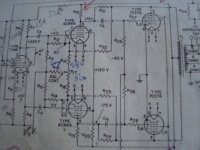
Interestingly, also thrown in the configuration are the bootstraps from 6CB6 cathodes to input grids, nicely upping the AC input Z, (reducing the loading effect on the concertina).
Rich, I see that resistor network R12-R9 as a tap across the voltage developed across R16 in oder to apply grid bias to the pentode, made necessary by the direct coupling of the NFB loop. This is similar to the Fred Nachbaur example I referred to (at http://mysite.du.edu/~etuttle/electron/elect35.htm). Admittedly, Fred's circuit is not the same as your example, a big difference being that Fred didn't have the plate-plate NFB connexion, just plate-cathode.
I'm modeling a similar amp right now, using LTspice. It uses 6AU6 drivers and has a 6SN7 cathodyne front end with a global NFB loop.
It looks good, but no better than a couple of other favorites of mine, a fully differential 6SL7 : 6SN7 : EL34 and a "Mullard" style 6SL7 "beta follower" : 6SN7 : EL34.
It looks good, but no better than a couple of other favorites of mine, a fully differential 6SL7 : 6SN7 : EL34 and a "Mullard" style 6SL7 "beta follower" : 6SN7 : EL34.
ray-moth, I'm suprised that Fed Nachbaurs example makes no attempt to correct for misbalances. Okay only 10W but even so for the physics it could have been optimised.
If the cathodes of the diff driver were joined, then in perfect balance one would see 2f or double the input frequency. Interestingly, if one puts a scope probe on this, as same time raising freqency, one starts to see dissimiliar amplitudes pertaining to misbalanced driver tubes but the stage correctly balances this.(as it should do)
The proof is thd and IMD examination. I am strongly convinced this intermediate stage requires true class A running at 10-30mA to satisfy quenching the Miller effect from most large power tubes. It's no use going into early slewing which I am convinced why the Mullard 5-20 sounds dull. Morgan Jones p.417 3rd edit. The use of an ECC83 driving power tubes has been often vented.
This is one of my critics of his book; not really covering driver politics in greater detail, such an important bandwidth issue. Power supplies using mosfets is also another area greatly missed, but understandably mosfets in psu's require some skill to get right..
However I can see his point that Morgan Jones amp 50W amp using KT88's requires 700V B+ for the driver, or is this a misprint ?
richj
We talked about the KT88 amp in another thread; it was more of a pedagogical exercise than a practical amp to build.
I'm thoroughly unconvinced by the notion of having a 30 mA standing current through a driver stage. What is wrong with running a driver as a very linear voltage amp, then buffering it from the output stage? With an AB amp, the buffer itself doesn't even need to be class A as long as it's source impedance at small signal is low enough to push the pole out a decade above the output transformer; at large signals, the source impedance (on the half cycle that counts) is even lower.
I'll confess to using a 700V driver stage, but as a feeble defense, my amp requires a LOT of voltage drive to the finals (sweep tube, screen-driven) and I run it as a split-rail, +/-350V.
SY, two opposing directions !....I go for high current low B+,350V; results may end up the same. I opt for simplistic designs. The reason why I opt for high current drivers is that parallel p-p pairs of 6550 in fixed bias suggest 50K grid leaks. This is awfully low (on the limits) for a diff config stage with anode output drivers, hence the increased current with lower anode resistances.
I did some checks on a Williamson diff phasesplitter driver, commonly used in the GEC 100W design, requiring around 50+50V rms o/ps for 50W and found it gave 5% thd feeding into 68K grid leaks before global nfb was added. This seems high, but 20dB of gobal nfb will drop total amp thd down to 0.5%.
With a concertina feeding into a Williamson diff stage with bootstrap feedback from driver cathodes to grid, one should expect around 1% thd from the diff drivers at the same 50+50V rms o/p voltage into far lower 40K+40K loads. Assuming good tubes.
richj
- Status
- This old topic is closed. If you want to reopen this topic, contact a moderator using the "Report Post" button.
- Home
- Amplifiers
- Tubes / Valves
- What splitter for this design ?