Hi Poindexter,
In most of the SRPP's, the 2 resistors are of the same values.
What is the reason to use slightly different ones in your circuit?
I have some 6T4's on the way to me. I know it will work when wiring as it is, but it is always good to know the "why" for the interest of learning something")
Thanks!!
In most of the SRPP's, the 2 resistors are of the same values.
What is the reason to use slightly different ones in your circuit?
I have some 6T4's on the way to me. I know it will work when wiring as it is, but it is always good to know the "why" for the interest of learning something
Thanks!!
Fred, you can use the same value resistor if you like; most people do. The upper tube (the active load) in an SRPP is not acting as an actual current source, it doesn't have enough gm to do so; that's the rationale behind the extra resistor (and associated capacitor) in a mu-follower, to give the load tube a bigger signal. If you look at the plate curves of any triode, you'll see that the equal-grid voltage curves are the steepest slope (lowest plate resistance) and farthest apart (highest transconductance) up in the upper left hand corner of the graph - low volts and high current. Now, since the two devices are in series, they'll always draw the same current, but if the cathode resistor for the load tube is of a smaller value, that device will drop less voltage, and so have a little higher gm.
It's a way of giving the circuit a little better balance between the amplifier and load devices. The improved balance reduces output hum (improves PSRR) a little, too.
Aloha,
Poinz
It's a way of giving the circuit a little better balance between the amplifier and load devices. The improved balance reduces output hum (improves PSRR) a little, too.
Aloha,
Poinz
Those will work fine, Fred. When I make for use in Europe, I use a Hammond 182E117 toroid, and get about 122Vdc out, which is enough. With 75Ω on the lower cathode and 68Ω on the upper, you'll draw about 20-21mA in the circuit, which will give a Vg-k on the amplifier of 1.5V. Since the cathode swings with the grid about 30%, there's your 2V line standard on the grid, which will give 10-11Vac out.
Yer in bizniz!
Aloha,
Poinz
Yer in bizniz!
Aloha,
Poinz
uH on Choke in Poinz's Power Supply
Hi Poinz (or whoever has a clue more than I),
I noticed you 6aq5 pre PS has a 9uH choke but your 6t4 pre PS has 25uH choke. The caps are the same.
Is there a reason for the big difference?
Is the 25uH also using internal resistance to drop the V a bit?
If one had a smaller choke, of say 10, 15 or 20uH available, would it be okay in the 6t4 PS?
Word.
Worst case, you could put a 270Ω resistor in there or something, to get going. I used the 9H Hammond (it's Henries, by the way, not microHenries) or 10H Triad until I found the 25H Tonyaba at Chung's (VT4C Studio) for the same price. You could use any of them, gotta love DIY. Myself, I like big chokes. One of the Golden Daze geniuses quoted in Sound Practices said, 'If your choke isn't as big as your power tranny, you ain't doin' it right.'
The trick with Chung, by the way, is to wander through his whole site (there are bargains and kewl tewls galore), and make up a good sized order, couple hundred clams or so. The kicker is shipping from Hong Kong, which will kill you on one choke.
Aloha Kakou,
Poinz
Poindexter said:Word.
... I found the 25H Tonyaba at Chung's (VT4C Studio) for the same price. You could use any of them, gotta love DIY. Myself, I like big chokes.... The kicker is shipping from Hong Kong, which will kill you on one choke.
Aloha Kakou,
Poinz
Yeah, i googled 25H 50mA and found that site. Don't know if there's enough stuff there to warrant and order yet. Depends on which project I try to bite off first.
Well, after reading Poinz description of the moebius as the daddy of them all - and it beating the aikido - I just had to have a go.
I had a good few of the parts already (iron) but needed the passives and valves. Radio daze had the valves at $2 ea, so I got 2 sets of 4, GE and RCA I think. So I have this rule - the chassis must be built first(!) otherwise I'd ever be allowed in to the house with the stuff (and I have small kids so the stuff must be safe).
so the chassis is now done and I have the transformers/chokes mounted and the PS wired. I need to do the signal stuff next and then the actual circuit.
I'm building it as a traditional build with a wooden chassis/alu top plate. 6 input, 1 output, stepped attenuator, separate switch for heaters and B+. Wire is all silver-in-teflon stuff. The only bit I'm not really sure of is the 6way 4 pole switch - I bought it off ebay - its gold flashed etc, but feels pretty clunky in use. Its very neat and small though, which suits the chassis. If it does prove to be flaky, I can always swap it out later.
Its not that i don't believe you Poinz, but I have had my 24V aikido up against a few amps now and it really holds its own with the best of stuff out there. So if this one is even as good as it, thats a pretty high recommendation!
I'll post a few pics in the next few days. I'm dreading a hum issue, but am paying good attention to payout etc as I go. Fingers crossed!
Fran
LOL, that's what I started this weekend, too!!
Since I am no good in chassis work (wood or metal ), I wanted to make sure my parts would work first before punching and drilling holes here and there. I wired up one channel on a cardboard to sort out the power supply. A couple things that I learned:
1. Keep the B+ within 140 if possible, don't go much higher than that. My 6T4's really didn't like exceeding the max cathode to heater voltage.
2. Keep the heater voltage at as close to 6.3 as possible. I had 6.6 at the beginning. It buzzed like a bee hive. Then I lowered it too much to 6.1, the current drawn was reduced which in turned caused the B+ to go up.
At the present state, it draws around 18ma at 141 B+ and heater is a little higher than 6.3, my pos dmm flip flop betweem 6.3 and 6.4.
PS, the Hammond 115 pri/ 120 sec isolation transformer that I used gave 119 VAC / 141 VAC in the real world. The sec is at least 15V higher than I expected!! That's how I found out my 6T4's didn't like the higher B+.
Since I am no good in chassis work (wood or metal
), I wanted to make sure my parts would work first before punching and drilling holes here and there. I wired up one channel on a cardboard to sort out the power supply. A couple things that I learned:1. Keep the B+ within 140 if possible, don't go much higher than that. My 6T4's really didn't like exceeding the max cathode to heater voltage.
2. Keep the heater voltage at as close to 6.3 as possible. I had 6.6 at the beginning. It buzzed like a bee hive. Then I lowered it too much to 6.1, the current drawn was reduced which in turned caused the B+ to go up.
At the present state, it draws around 18ma at 141 B+ and heater is a little higher than 6.3, my pos dmm flip flop betweem 6.3 and 6.4.
PS, the Hammond 115 pri/ 120 sec isolation transformer that I used gave 119 VAC / 141 VAC in the real world. The sec is at least 15V higher than I expected!! That's how I found out my 6T4's didn't like the higher B+.
I am running a separate DC linear supply for the heaters so I can adjust them pretty tight...
My off load B+ is up at 151VDC - I must put in a dummy load and see how it drops. My choke would be a bit lower than Poinz's rec, its probably about 5H with 40R DCR. Its actually 2 fluorescent ballasts in series. PSUD gives low ripple (0.02mV) and 140VDC with a 40mA loading. So I'm hoping it settles OK under load.
I hope to do more tonight so I'll post more then
Fran
Ok,
i got it put together last night. Sounds very sweet - but thats just out in the workshop with POS speakers, t-amp and ipod. No hum to speak of.....
but I do have a strange power supply problem. I'm seeing voltage on the chassis. There is a ground strap from the 100V transformer thats just bolted to the inside of the Tx frame and I'm measuring 65V from it to the windings - from what I can figure out I think that should be treated as if it were electrical earth and I should see the full AC voltage whether the primary of secondary across it. Connecting chassis to earth causes the ELCB to trip.
So progress in that theres no hum, but problems with power!
Fran
OK,
got my power sorted out. It was a bad transformer - the clue was a floating voltage on the chassis of about 1/2 the secondary voltage. I reckoned from secondary to either live or neutral I should have had the full secondary voltage (ie like earth).
So I stuck in a oversized 240-110 toroidal (100VA I think!) and it works now bang on. B+ is at 132VDC and seems stable. Most importantly the amp is quiet with no much hum that I can hear more than 2ft from the speaker. There is a little hiss, but again any more than 2ft and you won't hear it. Plenty of gain too I think without going overboard. I used a 50K pot in the end for attenuation and I think that the range will end up from say 6 o'clock to maybe 12. Not too bad a range really with a good bit of overhead still available. I have a concern about the pot - I didn't like it at all in the aikido, so I might do something else for this (maybe a lightspeed attenuator!).
Attached is an upskirt pic, not the tidiest, but at least its hum free. You can see the linear supply for the heaters and the fluorescent ballasts in series for a choke. Wimas for output caps. Other than that its fairly standard really.
Out in the workshop it sounds pretty nice, but thats just with an ipod and t-amp and really POS speakers! When I get it mounted on the chassis, the attenuator changed, knobs made and a cover for the toroidal Tx I'll be bringing it in and putting it up against the aikido. That will be interesting! How is yours coming pchw?
Fran (who is really happy that it is hum free!)

got my power sorted out. It was a bad transformer - the clue was a floating voltage on the chassis of about 1/2 the secondary voltage. I reckoned from secondary to either live or neutral I should have had the full secondary voltage (ie like earth).
So I stuck in a oversized 240-110 toroidal (100VA I think!) and it works now bang on. B+ is at 132VDC and seems stable. Most importantly the amp is quiet with no much hum that I can hear more than 2ft from the speaker. There is a little hiss, but again any more than 2ft and you won't hear it. Plenty of gain too I think without going overboard. I used a 50K pot in the end for attenuation and I think that the range will end up from say 6 o'clock to maybe 12. Not too bad a range really with a good bit of overhead still available. I have a concern about the pot - I didn't like it at all in the aikido, so I might do something else for this (maybe a lightspeed attenuator!).
Attached is an upskirt pic, not the tidiest, but at least its hum free. You can see the linear supply for the heaters and the fluorescent ballasts in series for a choke. Wimas for output caps. Other than that its fairly standard really.
An externally hosted image should be here but it was not working when we last tested it.
Out in the workshop it sounds pretty nice, but thats just with an ipod and t-amp and really POS speakers! When I get it mounted on the chassis, the attenuator changed, knobs made and a cover for the toroidal Tx I'll be bringing it in and putting it up against the aikido. That will be interesting! How is yours coming pchw?
Fran (who is really happy that it is hum free!)
Hi Fran,
I didn't work on the 6T4 pre since Sunday. The load at work is killing me (and I am taking a break now) You are making real good progress. Is the module in the top-left of the picture the power supply? Also, how much current is drawn from each channel? It is going to be interesting to hear from you the comparison between this and the Aikido which I never finish
I didn't work on the 6T4 pre since Sunday. The load at work is killing me (and I am taking a break now
) You are making real good progress. Is the module in the top-left of the picture the power supply? Also, how much current is drawn from each channel? It is going to be interesting to hear from you the comparison between this and the Aikido which I never finish yeah, that part is the heater supply. Its a 5V linear PS from salvage. They are adjustable voltage and also have current limiting and voltage sensing should you want it. One of those is also what I used for the 24V aikido - I adjusted it up as high as it would go and then added in a CLCRC filter for extra smoothing (in the aikido). They go on ebay for about $30 or so. Its really handy for DC heaters where the current draw isn't that high.
The heaters are drawing about a amp or so, but I have yet to measure the tube current yet. My B+ is a little lower than poindexters, about 132V as opposed to his 138V, but I still used the 75R/82R as per the schematic rather than the 68R/75R that he recommends for 110V Tx.
Seeing as I had the Tx, heater supply and chokes, this pre will stand me about $70 to make, including switches, tubes and RCAs. Not bad!
Fran
Interesting; I have never found DC heater supplies necessary, and the directly heated crowd hate 'em. I would doubt that it makes any difference for indirectly heated tubes, but:
Fran, you should take care in two respects. First, since your heater voltage is adjustable, keep it at or slightly below 6.3v; if you look in my schems, you will see small-value resistors in the heater line labeled 'Rdrop', which I value to set my own heaters at 6.2v. Second, be sure that you reference the heater voltage to an elevation of 25v above ground, as I do, to observe the very restrictive heater-cathode voltage of the 6T4, which is 50v down or 25v up from the cathode (!).
These two precautions will ensure practically infinite lifetime for your precious no-longer-manufactured lovely 6T4s.
Aloha,
Poinz
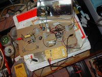
Today, the main is a little over 120VAC, comparing to 118.5 Sunday. The B+ shot up 4VDC to 145. The upper cathode was measured at 83, and the CT of the heater was at 24.5. The upper cathode has exceeded the limit, hmmm, no good. Need to drop a few more volts.
BTW, here is how one channel stands on the cardboard. The goal is to fit 2 channels with only one input into the aluminum box on the top-right
BTW, here is how one channel stands on the cardboard. The goal is to fit 2 channels with only one input into the aluminum box on the top-right
Attachments
- Status
- This old topic is closed. If you want to reopen this topic, contact a moderator using the "Report Post" button.
- Home
- Amplifiers
- Tubes / Valves
- What preamp should I build?