Nur keine Hektik, bitte! Take a Red Bull but only one of the small.
The TL072 or whatever you have replaced it with is supposed NOT to oscillate due to the 22pF. The 22pF does not create oscillation.
First problem, no supply voltage. If the LM2575T pin 1 has more than 12V on it, pin 4 is around 0V and pin 5 is "low", that chip is fried. You may check that there is no activity on pin 3 for verification.
You can temporarily use a 7812 but it will be warm. Put a heatsink on it and keep a fan going permanently. Be aware of the particular 7812 pin-out. Make sure you have some 100nF-470nF between the 7812 output and ground and short-circuit the LM2575 output choke for the time being.
Without a supply voltage there is no need to worry about anything else for the time being.
Last edited:
Nur keine Hektik, bitte! Take a Red Bull but only one of the small.
The TL072 or whatever you have replaced it with is supposed NOT to oscillate due to the 22pF. The 22pF does not create oscillation.
First problem, no supply voltage. If the LM2575T pin 1 has more than 12V on it, pin 4 is around 0V and pin 5 is "low", that chip is fried. You may check that there is no activity on pin 3 for verification.
You can temporarily use a 7812 but it will be warm. Put a heatsink on it and keep a fan going permanently. Be aware of the particular 7812 pin-out. Make sure you have some 100nF-470nF between the 7812 output and ground and short-circuit the LM2575 output choke for the time being.
Without a supply voltage there is no need to worry about anything else for the time being.
Hi FF
well done your german lesson...

") i do not drink REd Bull.......to much sugar.......Guten Morgen aus Wien
i do not drink REd Bull.......to much sugar.......Guten Morgen aus Wienthank you for your hints. actually the LM2575T is not working...the board is dark. this week i try something to solve that...thx
do you have an idea which low noise regulator is better?...instead of LM2575-series..same pin layout ..because i rechecked xyesterday all my working boards and its the same "noise" on each board.....peaks about vpp110mV...or on the pin V+ of the opamp. it does not matter which version of the board. LM2575t-12 or the combination LM2575S + LM317
i think i should investigate more in learning about regulators
chris
Last edited:
Hi FF
well done your german lesson...
thank you for your hints. actually the LM2575T is not working...the board is dark. this week i try something to solve that...thx
do you have an idea which low noise regulator is better?...instead of LM2575-series..same pin layout ..because i rechecked xyesterday all my working boards and its the same "noise" on each board.....peaks about vpp110mV...or on the pin V+ of the opamp. it does not matter which version of the board. LM2575t-12 or the combination LM2575S + LM317
i think i should investigate more in learning about regulators
chris
Gute Morgen aus die Berge,
You have two simultaneous effects causing high frequency noise: an SMPS with a moderately designed output filter and dominant digital consumption in parallel with delicate analog consumption. Though the PSRR of OP-AMPS is generally good, such supply noise can influence their performance.
I need to occupy myself with something else this morning but later I will study my previous findings on the TPA3255 board supply. I will return........
do you have an idea which low noise regulator is better?...instead of LM2575-series..same pin layout ..because i rechecked xyesterday all my working boards and its the same "noise" on each board.....peaks about vpp110mV...or on the pin V+ of the opamp. it does not matter which version of the board. LM2575t-12 or the combination LM2575S + LM317
chris
you should learn about measurements. Peaks of some hi-frequency content measured with a scope do not necessarily relate to audible noise.
you should learn about measurements. Peaks of some hi-frequency content measured with a scope do not necessarily relate to audible noise.
yes you are right.....thats the reason i am still learning and try to be a DIY
Hi Chris,
I did a little calculation on the blue TPA3255 board with the components that were initially put on the board. You can then tell me what you have changed on the board where the power supply broke down.
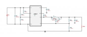
The LM2575 operates at 52KHz. It uses a 22uH/22uF output filter. 22uF at 52KHz leaves an impedance of 0.14 Ohm. 22uH at 52KHz leaves an impedance of 7.2 Ohm. A rough estimation concludes that the output voltage ripple for this filter is in the order of 1.9% of the input ripple (at 52KHz). With 28Vpp in, that means 0.53Vpp out.
22uH is a surprisingly low value and the datasheet suggests 330uH. With 330uH instead, the output ripple is divided by 15. Even with 330uH, some visible residual of the switching frequency will be found at the output.
A Buck converter (step-down), like the LM2575, has a good power conversion efficiency but the output has significant ripple and the SMPS may radiate noise.
An alternative to the step-down switch mode converter is the linear regulator. A linear regulator has little output ripple (in principle none) and a better step response because the bandwidth normally is higher. The (only) disadvantage of the linear regulator is the power loss that necessitates a rather bulky heatsink. And, a linear regulator can only reduce voltage.
Why does the blue TPA3255 board use a step-down SMPS if a linear regulator has better performance? Lets look at the supply voltages and currents needed:
12V/ 44mA (typ.) for the TPA3255 chip GVDD input. Digital circuit consumption.
12V/ 30mA (typ.) for the TPA3255 chip VDD input. Digital circuit consumption.
12V-30V for the four OP-AMPs (initially TL072). The typical power consumption of a TL072 is 1,5mA per amplifier. With the better LM4562, the consumption increases to 10mA (typ.) per amplifier.
Hence, we need around 75mA (typical) at 12V for digital circuit consumption inside the TPA3255 chip. With some tolerance, we should design for 100mA.
And, we need between 6 and 40mA (typical) at 12V-30V for analog consumption in the four OP-Amps. We should design for >60mA.
That may be a lot of energy wasted as heat in a linear regulator.
How was that need solved by the initial board design? They used a Buck SMPS to reduce the input voltage to 15V and a post-regulator (linear / LM317 based) to reduce the ripple. Thus, all consumption (from digital circuits and the four OP-AMPs) was drawn on the same 12V line. That left the problem of the digital circuit consumption (which is the dominant) introducing noise on the supply line of the delicate OP-AMPs. Further, the OP-AMPs had only 12V for their operation which does in most cases not allow superior THD performance.
The advantage was that the SMPS would handle the large voltage drop with high efficiency and the post-regulator would remove the worst supply-line ripple and noise. It would not take up much space on the PCB.
The job of a power engineer is to find the best compromise for the given needs:
1) 12V/100mA digital circuit consumption,
2) 12V-30V/ >60mA analog circuit consumption,
3) A bit of low-voltage and low-power consumption. Not a problem.
How do we combine linear regulators and SMPS the best?
Myself I chose, as a non-ideal solution (posting #303), to use two cascaded LM317 (with heatsinks) such that the first LM317 reduces the input voltage to 24V. The 24V is used for the OP-AMPs and leaves good supply for low THD performance. Further, the 24V is reduced to 12V by the second LM317 and used for the digital circuit consumption inside the TPA3255 (and the control circuits). The 12V consumption can return some current ripple to the 24V line but the noise is attenuated by the decoupling capacitors. None of the LM317 introduce any switching noise such as if an SMPS is used. The disadvantage is that the heatsinks became a bit warmer than I like and I normally use a slow running fan. I had to put the new power and OP-AMP circuits on an additional board because the existing PCB could not be modified to that extent.
How do we find a (almost ideal) solution for your board?
Please let me know how your board today differs from the description of my initial board?
I did a little calculation on the blue TPA3255 board with the components that were initially put on the board. You can then tell me what you have changed on the board where the power supply broke down.
The LM2575 operates at 52KHz. It uses a 22uH/22uF output filter. 22uF at 52KHz leaves an impedance of 0.14 Ohm. 22uH at 52KHz leaves an impedance of 7.2 Ohm. A rough estimation concludes that the output voltage ripple for this filter is in the order of 1.9% of the input ripple (at 52KHz). With 28Vpp in, that means 0.53Vpp out.
22uH is a surprisingly low value and the datasheet suggests 330uH. With 330uH instead, the output ripple is divided by 15. Even with 330uH, some visible residual of the switching frequency will be found at the output.
A Buck converter (step-down), like the LM2575, has a good power conversion efficiency but the output has significant ripple and the SMPS may radiate noise.
An alternative to the step-down switch mode converter is the linear regulator. A linear regulator has little output ripple (in principle none) and a better step response because the bandwidth normally is higher. The (only) disadvantage of the linear regulator is the power loss that necessitates a rather bulky heatsink. And, a linear regulator can only reduce voltage.
Why does the blue TPA3255 board use a step-down SMPS if a linear regulator has better performance? Lets look at the supply voltages and currents needed:
12V/ 44mA (typ.) for the TPA3255 chip GVDD input. Digital circuit consumption.
12V/ 30mA (typ.) for the TPA3255 chip VDD input. Digital circuit consumption.
12V-30V for the four OP-AMPs (initially TL072). The typical power consumption of a TL072 is 1,5mA per amplifier. With the better LM4562, the consumption increases to 10mA (typ.) per amplifier.
Hence, we need around 75mA (typical) at 12V for digital circuit consumption inside the TPA3255 chip. With some tolerance, we should design for 100mA.
And, we need between 6 and 40mA (typical) at 12V-30V for analog consumption in the four OP-Amps. We should design for >60mA.
That may be a lot of energy wasted as heat in a linear regulator.
How was that need solved by the initial board design? They used a Buck SMPS to reduce the input voltage to 15V and a post-regulator (linear / LM317 based) to reduce the ripple. Thus, all consumption (from digital circuits and the four OP-AMPs) was drawn on the same 12V line. That left the problem of the digital circuit consumption (which is the dominant) introducing noise on the supply line of the delicate OP-AMPs. Further, the OP-AMPs had only 12V for their operation which does in most cases not allow superior THD performance.
The advantage was that the SMPS would handle the large voltage drop with high efficiency and the post-regulator would remove the worst supply-line ripple and noise. It would not take up much space on the PCB.
The job of a power engineer is to find the best compromise for the given needs:
1) 12V/100mA digital circuit consumption,
2) 12V-30V/ >60mA analog circuit consumption,
3) A bit of low-voltage and low-power consumption. Not a problem.
How do we combine linear regulators and SMPS the best?
Myself I chose, as a non-ideal solution (posting #303), to use two cascaded LM317 (with heatsinks) such that the first LM317 reduces the input voltage to 24V. The 24V is used for the OP-AMPs and leaves good supply for low THD performance. Further, the 24V is reduced to 12V by the second LM317 and used for the digital circuit consumption inside the TPA3255 (and the control circuits). The 12V consumption can return some current ripple to the 24V line but the noise is attenuated by the decoupling capacitors. None of the LM317 introduce any switching noise such as if an SMPS is used. The disadvantage is that the heatsinks became a bit warmer than I like and I normally use a slow running fan. I had to put the new power and OP-AMP circuits on an additional board because the existing PCB could not be modified to that extent.
How do we find a (almost ideal) solution for your board?
Please let me know how your board today differs from the description of my initial board?
Hi Chris,
I did a little calculation on the blue TPA3255 board with the components that were initially put on the board. You can then tell me what you have changed on the board where the power supply broke down.
The LM2575 operates at 52KHz. It uses a 22uH/22uF output filter. 22uF at 52KHz leaves an impedance of 0.14 Ohm. 22uH at 52KHz leaves an impedance of 7.2 Ohm. A rough estimation concludes that the output voltage ripple for this filter is in the order of 1.9% of the input ripple (at 52KHz). With 28Vpp in, that means 0.53Vpp out.
22uH is a surprisingly low value and the datasheet suggests 330uH. With 330uH instead, the output ripple is divided by 15. Even with 330uH, some visible residual of the switching frequency will be found at the output.
A Buck converter (step-down), like the LM2575, has a good power conversion efficiency but the output has significant ripple and the SMPS may radiate noise.
An alternative to the step-down switch mode converter is the linear regulator. A linear regulator has little output ripple (in principle none) and a better step response because the bandwidth normally is higher. The (only) disadvantage of the linear regulator is the power loss that necessitates a rather bulky heatsink. And, a linear regulator can only reduce voltage.
Why does the blue TPA3255 board use a step-down SMPS if a linear regulator has better performance? Lets look at the supply voltages and currents needed:
12V/ 44mA (typ.) for the TPA3255 chip GVDD input. Digital circuit consumption.
12V/ 30mA (typ.) for the TPA3255 chip VDD input. Digital circuit consumption.
12V-30V for the four OP-AMPs (initially TL072). The typical power consumption of a TL072 is 1,5mA per amplifier. With the better LM4562, the consumption increases to 10mA (typ.) per amplifier.
Hence, we need around 75mA (typical) at 12V for digital circuit consumption inside the TPA3255 chip. With some tolerance, we should design for 100mA.
And, we need between 6 and 40mA (typical) at 12V-30V for analog consumption in the four OP-Amps. We should design for >60mA.
That may be a lot of energy wasted as heat in a linear regulator.
How was that need solved by the initial board design? They used a Buck SMPS to reduce the input voltage to 15V and a post-regulator (linear / LM317 based) to reduce the ripple. Thus, all consumption (from digital circuits and the four OP-AMPs) was drawn on the same 12V line. That left the problem of the digital circuit consumption (which is the dominant) introducing noise on the supply line of the delicate OP-AMPs. Further, the OP-AMPs had only 12V for their operation which does in most cases not allow superior THD performance.
The advantage was that the SMPS would handle the large voltage drop with high efficiency and the post-regulator would remove the worst supply-line ripple and noise. It would not take up much space on the PCB.
The job of a power engineer is to find the best compromise for the given needs:
1) 12V/100mA digital circuit consumption,
2) 12V-30V/ >60mA analog circuit consumption,
3) A bit of low-voltage and low-power consumption. Not a problem.
How do we combine linear regulators and SMPS the best?
Myself I chose, as a non-ideal solution (posting #303), to use two cascaded LM317 (with heatsinks) such that the first LM317 reduces the input voltage to 24V. The 24V is used for the OP-AMPs and leaves good supply for low THD performance. Further, the 24V is reduced to 12V by the second LM317 and used for the digital circuit consumption inside the TPA3255 (and the control circuits). The 12V consumption can return some current ripple to the 24V line but the noise is attenuated by the decoupling capacitors. None of the LM317 introduce any switching noise such as if an SMPS is used. The disadvantage is that the heatsinks became a bit warmer than I like and I normally use a slow running fan. I had to put the new power and OP-AMP circuits on an additional board because the existing PCB could not be modified to that extent.
How do we find a (almost ideal) solution for your board?
Please let me know how your board today differs from the description of my initial board?
Thanks you my friend....thats very detailed and i am able to follow you.
its exactly what you designed in the summer. you did your own input circuit.
the actually board has just the LM2575T-12 without the LM317.
so the ripple and power is handled by 1 chip =LM2575T-12.
i changed the 3 caps near the regulator to 220µF/35V each
my both boards amp 5 (AD8599) and my amp7 (opa1602) use the same configuration = one chip for the 12V = LM2575T-12 both boards are sounding fine and are working well. so no power issue...clipping...oscillation
as i wrote in post 522. i guess the 220µH is not correct accord. to the datasheet. i don´t know if L=220µH is too bad for this.
the damaged board has just the original coil 22µH..because i run out of my coils with 220µHand the caps changed to 220µF
thank you FF
Just to make sure I understand you right, all your boards use LM2575T-12 only. The other boards have 220uH chokes but the defect board a 22uH choke. You have increased the filter output capacitance to 3x220uF and the other boards work and sound well.
There is an old saying: "If it works well, don't repair it".
If so, the defect board needs a new LM2575-12. Eventually you can use the variable version of LM2575. The 22uH choke should be changed to 220uH or 330uH which reduces the ripple a lot. With such, the broken board should also be back in action.
I put in IC sockets in my TPA3255 such that I can easily change the OP-AMPs. As I recall, I use OPA2134s that need 24V-30V to function well. With 12V supply you can find OP-AMP types that are better than OPA2134 or LM4562. Those you propose may be such with good low voltage operation. The rather new OPA16xx series should also have very low THD at 12V.
Let me know if the TPA3255 power supply still gives you trouble.
Last edited:
A more elegant approach is the "flybuck" converter using LM5019 or LM5017. Rated at max input voltage of upto 100V it delivers an output voltage of +/-12V for instance.
There is no additional linear reg involved.
This supplies the TPA325x 12Vinput as well as your op-amps with a symmetric supply - allowing high undistorted voltage swing and hi supply ripple immunity.
This solution does not take too much board space and works reasonably well in my TPA325x designs.
There is no additional linear reg involved.
This supplies the TPA325x 12Vinput as well as your op-amps with a symmetric supply - allowing high undistorted voltage swing and hi supply ripple immunity.
This solution does not take too much board space and works reasonably well in my TPA325x designs.
Attachments
A more elegant approach is the "flybuck" converter using LM5019 or LM5017. Rated at max input voltage of upto 100V it delivers an output voltage of +/-12V for instance.
There is no additional linear reg involved.
This supplies the TPA325x 12Vinput as well as your op-amps with a symmetric supply - allowing high undistorted voltage swing and hi supply ripple immunity.
This solution does not take too much board space and works reasonably well in my TPA325x designs.
A power converter with an asymmetrical power capability. More "+" power than "-" power. Very useful for this particular application where the OP-AMPs use around the same power from "+" and "-" while the TPA3255 needs only "+" power.
I hope this kind of creativity also succeeds with the popular suppliers of TPA3255 boards.
you nailed itA power converter with an asymmetrical power capability. More "+" power than "-" power. Very useful for this particular application where the OP-AMPs use around the same power from "+" and "-" while the TPA3255 needs only "+" power.
I hope this kind of creativity also succeeds with the popular suppliers of TPA3255 boards.
Just to make sure I understand you right, all your boards use LM2575T-12 only. The other boards have 220uH chokes but the defect board a 22uH choke. You have increased the filter output capacitance to 3x220uF and the other boards work and sound well.
There is an old saying: "If it works well, don't repair it".
If so, the defect board needs a new LM2575-12. Eventually you can use the variable version of LM2575. The 22uH choke should be changed to 220uH or 330uH which reduces the ripple a lot. With such, the broken board should also be back in action.
I put in IC sockets in my TPA3255 such that I can easily change the OP-AMPs. As I recall, I use OPA2134s that need 24V-30V to function well. With 12V supply you can find OP-AMP types that are better than OPA2134 or LM4562. Those you propose may be such with good low voltage operation. The rather new OPA16xx series should also have very low THD at 12V.
Let me know if the TPA3255 power supply still gives you trouble.
Hi FF
1.chapter - Yes , all correct
2. chapter
is there a big difference of 330µH or 220µH..according to the datasheet 220µH is not correct
3. chapter
i bought during the Fx502spro journey some opamps, some of them are just SOIC8 = AD8599 + opa1602 - so no socket possible...i want to try swapping amps so no problem to ahve mor then 1 board
4 I am back if the LM2575 is at home and the first tests startet.
thx
A power converter with an asymmetrical power capability. More "+" power than "-" power. Very useful for this particular application where the OP-AMPs use around the same power from "+" and "-" while the TPA3255 needs only "+" power.
I hope this kind of creativity also succeeds with the popular suppliers of TPA3255 boards.
 well designed voltwide
i played with this TI WEBench Power designer.....nice tool !!! you can use smal footprint or more efficiency... for LM5017 i set the low ripple design value...see attachment
thats fine for an old man like me
Attachments
sorry to badger you both
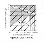
but can you explain me the figure 29 of the LM2575 datasheet please ???
because of:
i pick up the idea from sybic mods to change the 22µH to 220µH.
FF told me 330µH is ok...its in the datasheet example too
but if i look at the Voltage x axle and i use 28V input and approx 0,2 -0,3 Amper current drawing i shlud use H1500µH - 2200µH...but there is a "black zone"
what does it mean??? or how to calculate correctl?
thank you...
Attachments
2. chapter
is there a big difference of 330µH or 220µH..according to the datasheet 220µH is not correct
There is a range of inductors and capacitors you can use in the output filter. 220uH is not wrong. The rule is the bigger value for the inductor and capacitor, the less output ripple but at the same time lower filter cut-off frequency and less loop stability. When the LM2575 datasheet shows a 330uH/330uF output filter, they inform us that with the corresponding cut-off frequency the stability of the loop is fine. You can lower the inductor to 220uH and increase the capacitor to 470uF and you have close to the same cut-off frequency and loop stability.
The less the value of the inductor and the higher the value of the capacitor, the more "heavy" the filter becomes for the chip to operate because the total impedance (in series) is less. The higher the inductance, the physically bigger the choke needs to be to carry the DC current without saturation.
There are more factors to take into account at the same time, but 22uH/22uF is a filter with a strangely high cut-off frequency and high output ripple.
3. chapter
i bought during the Fx502spro journey some opamps, some of them are just SOIC8 = AD8599 + opa1602 - so no socket possible...i want to try swapping amps so no problem to ahve mor then 1 board
As long as you have short connecting wires a second board is possible. You should always aim at the signal being transferred from one board to another to be low impedance such that the wires pick up less noise.
4 I am back if the LM2575 is at home and the first tests startet.
Fine.
NB: I believe the exact phrasing of my colleagues was "If it ain't broke, don't fix it."
Last edited:
sorry to badger you both
but can you explain me the figure 29 of the LM2575 datasheet please ???
because of:
i pick up the idea from sybic mods to change the 22µH to 220µH.
FF told me 330µH is ok...its in the datasheet example too
but if i look at the Voltage x axle and i use 28V input and approx 0,2 -0,3 Amper current drawing i shlud use H1500µH - 2200µH...but there is a "black zone"
what does it mean??? or how to calculate correctl?
thank you...
Gray zones tend to leave us with a bad conscience even if we do not know what they mean.
Section 8,2.2.10 is really useful for designing the output filter, but Figure 12 is not well explained in all details. My first impression is that the gray zones indicate where you risk running into discontinuous choke current, thus, that the ripple current equals or exceeds the output DC current and stops or even reverses the current in the choke. I will have to think a little more.
As long as you have short connecting wires a second board is possible. You should always aim at the signal being transferred from one board to another to be low impedance such that the wires pick up less noise.
to be clear stated...i use a complete amp board to change for SQ check...not just the opmaps
- Home
- Amplifiers
- Class D
- What is wrong with TPA3255?