Any link to blue V2 board, please.
Hi Zek
Aliexpress - shop TZT
the fotos show a black borad in V1 config = LM2575S with LM317
but i got the blue board V2 - with LM2575T + AMS117-3,3
https://www.aliexpress.com/snapshot/0.html?spm=a2g0s.9042647.6.2.64ca4c4dj7CMZ3&orderId=506618667912124&productId=32902499503
chris
DC voltages about 6V are ok with a supply of 12V. To trace your pin6 phenomen a detailed circuit diagram of the OPA would be helpful.
I am not the expert but it should be the same as at the TI EVM boards.
MAybe doctor had some closer look if you fixed the pop noise.
Edit:
to make it clear
without input und power up the amps shuts down if i use DMM or scope probe on PIN 6 of the first OPAMP as you correct mentioned
strange ???
Last edited:
Thanks Chris for info.Hi Zek
Aliexpress - shop TZT
the fotos show a black borad in V1 config = LM2575S with LM317
but i got the blue board V2 - with LM2575T + AMS117-3,3
https://www.aliexpress.com/snapshot/0.html?spm=a2g0s.9042647.6.2.64ca4c4dj7CMZ3&orderId=506618667912124&productId=32902499503
chris
Link needs password.

Thanks Chris for info.
Link needs password.
ahh....sorry it is my account.
you just look at aliexpress for this TPA3255 300W board and look for the shop tzt. but as i wrote i got a blue board instead of black like the photo.
i really dont care which version...is stick on learning on this board and build some 4 ohm and 8 ohm amps.
If you measure DC coupled you see the DC bias as well, that is the DC voltage of the OPA output where the AC signal is centered. If it distorts on the neg excursion possibly this bias is to close to neg supply voltage.
.
so i measured but no wrong bias.
so whats next?
i solder all opamps and 10k resistors because it looks optical strange. but with the same result. with 9kz and more then 250mVrms i got a strange (clipping?) neg. sine.
i really appreciate your help
I had a look at your scope screenshots - and the degradation at 15kHz might indicate a very bad op-amp. Maybe your 5532 are fakes and in reality LM358 - this could explain the poor performance. So it could be a good idea to replace the OPA by something of well known quality - even TL072 should perform better here.
I had a look at your scope screenshots - and the degradation at 15kHz might indicate a very bad op-amp. Maybe your 5532 are fakes and in reality LM358 - this could explain the poor performance. So it could be a good idea to replace the OPA by something of well known quality - even TL072 should perform better here.
hi voltwide
ok.....Thanks you.
The opamps are the same as the other boards - TL02 "labeled"
neverhtless i plan to have different configured boards (4 ohms and 8ohms...) to make easy compare.
thx
chris
YJ TPA3255 ...using 2 amps
Hi
yesterday i think about having 2 amps splitted for speakers TT and HT.
so to try for the TT a 4ohm config (7µh + 680nF) and for the HT a 8ohms or 10ohms config (10µh + 680nF, 13µH + 680nF) --> a kind of bi amping
how to proceed with the RCA inputs to the 2 amps?
chris
Hi
yesterday i think about having 2 amps splitted for speakers TT and HT.
so to try for the TT a 4ohm config (7µh + 680nF) and for the HT a 8ohms or 10ohms config (10µh + 680nF, 13µH + 680nF) --> a kind of bi amping
how to proceed with the RCA inputs to the 2 amps?
chris
YJ blue board V2..opamps change ..fine
Hi
Thank you voltwide!
the problem at the blue board V2 (LM2575T-12V) is solved.
as you correct mentioned this opamps are fake. the light and the smartphone cam are not able to show you the label but the label ST is really strange designed
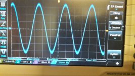
i changed now to the AD8599 and as you can see on the pic everything is fine over 200mVrms input.
the probe is set on the first opamps pin 1 with 470mVrms - 15kHz input signal.
thx
chris
Hi
Thank you voltwide!
the problem at the blue board V2 (LM2575T-12V) is solved.
as you correct mentioned this opamps are fake. the light and the smartphone cam are not able to show you the label but the label ST is really strange designed
i changed now to the AD8599 and as you can see on the pic everything is fine over 200mVrms input.
the probe is set on the first opamps pin 1 with 470mVrms - 15kHz input signal.
thx
chris
Attachments
Got my Chinese tpa3255 blue board. Is there a chance to power this stuff in higher voltage.. Maximum of 48 volts?? Thanks.
no. if you do not want to burn the voltage regulator on the board.
the chinese vendors use the TI TPA3255 chip value to promote the board with better power and performance.
the voltage regulator on the YJ TPA3255 is a LM2575S or LM2575T model and provide voltage for the opams( inputs) and some pins for the power amp = TPA3255.
the maximum recomended Voltage of the LM2575 S(T) is 40V - so use 2-3 volts less for your psu.
the power you "loose" is not needed. the heatsink and the general implementation at this board is not as strong as a original TI EVM board.
personally for appr. 40 euro this is a very nice board to try and play. I use a LRS 150-24V for 4ohm speakers and i am very satified with the power at home (26m²)
if you take your time and read from the beginning of this thread you will learn from my mistakes
and a lot of some experts and developers here.
yes....if you desolder the LM2575S (T) to a LM2575 Hv version. this can handle the 48V...personally i think its not needed...
chris
Last edited:
Hi
what do you want to spend on money? whats your budget for your amp?
if you use this board for subwoofer- boom box then its better to use a power board with huge heatsink -class D --IRS2092S...etc.
i did a test with about 40 min at 70 Watt/4ohm per channel and then the amp luckly swtich off = heatsink 102°celsius !!!!!
so this blue board implementation of the TPA cannot provide the max specification of the TI TPA3255 chip.
please think about what you really want to have.
opamp change? is not so easy. at this board the opamsp are SMD - so i expect that you have no experiance at soldering of SMD.... so do not plan this.
i try a lot at this board ...i start my journey at page 21
my minimum proposal is to change the input caps (2) of the rca jacks and the 4 pc. before the inputs of the power chip. the original silver caps are of bad quality. change this to some elna electrolyt silmic 2 caps 10µF /16V. so soldering 6 caps should be ok.
think about a psu by meanwell LRS 150-24V (set to 28V without load) about 21 euros!
chris
opamp SQ TL02 vs AD8599
Hi
after changing the opamp of one of my blue board v2 i did a sound check.
amp5 is now the board with. change output filter and muse caps at the inputs, the regulator caps are change to better electrolytic. and i set the 22mH to 220mH at the regulator...as i do at all boards. the decoupling caps are the original one.(Sanwu 4700µF/63V...after burn in 100 hours its at 8450µF for both..
amp6 is now the AD8599 board.
output filter is complete original (L=12,22µH , 12,23µH, 12,44µH , 12,45µH -all 4 caps are close to 1µF ) - same setup at the regulator -input caps are nichicon UHE and directly after the inputs is use the green muse 10µ
power up with my LRS150-24V(set to 28V), source is Tidal over usb diamond cable - Gustard A20H DAC
after4 day compare a lot of titles its clear for me -the cost for 2 opamps are about 20 euros and its better SQ!
the lower noise level is the big advantage in all kind of music, this give me the chance to get a better sound stage (deep and clear) and a fine settle out of all instruments. what i did not expected is a better bass, its not so bloated - more controlled - because of the better output coils at the amp5?
so the original coils are good enough for the "low" power of the living room for listening???? - i will build another board with better opamp and better output filter coils for compare..
i did not expect because the output filter is too high set = 12,2µH and my speakers are about 4-5 ohms.
the pdf shows the frequency response at the real board = amp6
the simulation (TI designer) shows different
chris
Attachments
Last edited:
- Home
- Amplifiers
- Class D
- What is wrong with TPA3255?