Grid emission is part of the grid leakage (gas being a much larger contributor). If grid emission is high, that resistance value has to be lower. See pp 315-316 in Valve Amplifiers 4th ed. It's made worse by temperature (Richardson-Dushman)- note that a unipotential cathode will operate at 1100-1200k, whereas a filamentary cathode will operate closer to 2000K, thus having much higher heating. This correlates with the higher grid currents characteristic of DHTs.
The cathode temperature does not determine the grid emission - rather the grid temperature. Sure the power derives from the cathode, but returning to the comparison of 300B and 6L6, the height of the grid in the 300B is more than 50% greater than 6L6, and the width more like 3x. And the grid is substantially further away from the cathode in the 300B. Now, given that the heating power is almost the same in both cases (~6W), how can the 300B grid be anything but cooler than that of the 6L6?
We tried DC and AC and preferred AC. AC can be done correctly or incorrectly. Ditto DC. But with DC, you can't get away from systematically uneven emission along the cathode. Unipotential has a huge advantage here.
Our experiments were done in the late 1970s, so I doubt you were selling your DHT heater supplies then.
The unipotential cathode is of course an advantage. But whatever gains the indirectly heated tubes make from that are fully reflected in the curves we examined earlier in this thread - which show the directly heated 300B to be a far better performer in the task we demand of it - namely driving a loudspeaker.
I am sure that ac would have been a better choice in those 1970s days, without doing the whole filament supply investigation DIY.
But the performance difference between best-and-worst ac is tiny compared to the corresponding change for dc techniques.
Now, given that the heating power is almost the same in both cases (~6W), how can the 300B grid be anything but cooler than that of the 6L6?
Equilibrium and the Zeroth Law of Thermodynamics.
Yes, in the 1970s, we had quite excellent regulators available to us. It may shock you, but we actually did some serious work on this. And as a result, I've never bothered with DHTs again.
Equilibrium and the Zeroth Law of Thermodynamics.
I'll take that as a no, then.
Yes, in the 1970s, we had quite excellent regulators available to us. It may shock you, but we actually did some serious work on this. And as a result, I've never bothered with DHTs again.
It does not shock me, but the whole just confirms that you and I have very different priorities, when it comes to listening, and design as well. That's OK - this is DIY.
wa2ise,
Think of upper frequency limit of the tube. Tubes would not have upper frequency limits in the MHz if the signal propagated at the speed of light. Rather they would have frequency limits that would be solely limited by physical construction with the frequency limit = d/s where d is the distance from cathode to plate and s is the speed of light.
A good explanation is in the Electronic Designers Handbook by Dundee on the top of the page 2-7 where he is discussing diodes.
The electric fields from the anode and grid do travel at the speed of light.
Doesn't the presence of the electron stream increase the permittivity of the 'vacuum'? Hence why the cold interelectrode capacitance are less than the hot capacitances?
The unipotential cathode is of course an advantage. But whatever gains the indirectly heated tubes make from that are fully reflected in the curves we examined earlier in this thread - which show the directly heated 300B to be a far better performer in the task we demand of it - namely driving a loudspeaker.
Rod is being overly modest here. The power supply he's been advocating in DIYAudio makes the DHT a unipotential cathode for signal, a very strong advantage.
The downside is that I now need to change my 845 stereo-on-one-chassis amplifier to his new thought. It weighs well over 100 pounds. Curses on the dummy who made it so heavy.
Thanks,
Chris
Yes, but Rod Coleman's power supply is a high impedance source for signal frequencies. He doesn't claim it to be a unipotential cathode, but I'd call it that because the whole (filamentary) cathode floats up and down with signal. Your description is of course more correct, but his power supply is unique to my experience. All others put different portions of the (filamentary) cathode at slightly different signal voltages, depending on the power supply's low internal source impedance and the filament's low internal wire impedance to try to keep all parts unipotential for signal.
Thanks
Chris
Thanks
Chris
Yes, but Rod Coleman's power supply is a high impedance source for signal frequencies.
It does not matter. When the control voltage applied between grid and cathode it swings on different level on different ends of the cathode. It shows as decrease of linearity wen the control voltage approaches close to zero volt. That means, they could be more linear if cathode had true equal potential in any it's point. But the result anyway is superb, especially when filtered DC is applied. In case of AC this differences on voltages on opposite points of the filament are not zero. They are variable. Being added to the control signal they add hum and cause inter-modulation between this AC and control signal.
If his supply is high impedance for signal frequencies then it will need to be bypassed.
Rod recommends just tying one side to ground. I suggested the old two-equal-resistor divider, but apparently it's not needed. (I'll do it anyway - old school.)
Thanks,
Chris
I should also add that the Rod Coleman circuit has very little "common mode" voltage overhead, in the interest of efficiency. Beyond a volt or two signal, performance would rely on upstream parts of the power supply for isolation. No big deal for conventional use of course.
Thanks,
Chris
Thanks,
Chris
But with DC, you can't get away from systematically uneven emission along the cathode.
You mean uneven current over the length of the filament as controlled by a unipotential grid (I know, grids are always unipotential). But the 300B looks to be quite linear, and thus the Gm (Gm=(variation of output current)/(variation of input voltage)) looks to be the same over a 5V DC bias variation. Meaning that the Gm contribution of a section of filament near the positive filament supply is the same as the same size section near the middle, and same size as a portion near the negative filament supply. And that variation of voltage and current is our audio signal. And 5V is much less than the 61V peak audio voltage for the grid as it says in the Bell System spec sheet http://www.mif.pg.gda.pl/homepages/frank/sheets/084/3/300B.pdf
Rod recommends just tying one side to ground. I suggested the old two-equal-resistor divider, but apparently it's not needed. (I'll do it anyway - old school.)
Thanks,
Chris
Hi Chris,
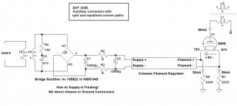
The emphasis in my documents on the floating supply has to do with floating the raw dc and transformers, to allow any dc voltage to be set on the 300B "cathode". So the input side floats, but the output can be connected to ground, or it can ride on a cathode autobias resistor at any voltage desired.
If you like to use 2 resistors, please try, and compare it with the circuit in my suggested connexion method. It does seem to have quite a big influence on the sound.
Another method is to autobias a DHT using 2 separate resistors. The picture shows the arrangement: the 2 ends of the filament are connected to ground using 2 separate resistors, whose values are set to allow half the cathode current to flow in each, while maintaining a voltage difference of Vf between the two resistors.
I don't insist that this sounds better than the usual connexion, but you may prefer the equalised current draw, if you're using autobias.
Attachments
Doesn't the presence of the electron stream increase the permittivity of the 'vacuum'? Hence why the cold interelectrode capacitance are less than the hot capacitances?
Nothing to do with permitivity. Interelectrode capacitance depends on geometry. Add the space charge, and that becomes part of the geometry of the control grid, making the effective plate area that much greater. There is even a voltage variable capacitance phenomenon somewhat similar to the parametric frequency multiplication of reverse biased PN junctions (though this arises in a different manner). Not that it makes all that much difference at audio frequencies.
a friend of mine has a 2A3 SET that was humming....simply replacing the old 2A3 tube with a fresh tube cured the humming, why is that?
Sorry, not enough detail to give you an answer. Some info that could help:
Schematic:
- DC or AC filaments?
- Balance pot circuitry?
- Operating spec?
History:
- Was it working properly at one point with the existing 2A3?
- Brand/type of 2A3 used (original and replacement)?
- Any notable events that happened when the problem occurred, i.e., power surge, etc.?
Regards, KM
afaik, ac filaments, and he had the amp for almost 4 years now....i suspect cathode depletion, can i be correct?
afaik, ac filaments, and he had the amp for almost 4 years now....i suspect cathode depletion, can i be correct?
Some modern production DHTs have a failure mode where only part of the filament is energised. This can be clearly seen through the glass as unlit filament. It's best not to try these again, as filament breakage failures can result in shorts, and OT damage.
Next, a loss of vacuum can occur, and 'gas' the triode. Gas means high grid current. In fixed bias amplifiers, this can upset the bias, and make the anode current to run much too high - in which case the hum stems from an overloaded dc supply (if, as usual, the supply is not able to support much extra dc current).
If the emission level is depleted, the anode current usually drops a little, and the amp sounds enfeebled. It may not hum, unless the degradation is accompanied by gas - see above.
- Status
- This old topic is closed. If you want to reopen this topic, contact a moderator using the "Report Post" button.
- Home
- Amplifiers
- Tubes / Valves
- What is the theoretical advantage of direct heated triodes?