
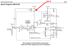
They implement a cheezy 2*fmains charge pump which provides a boosted voltage called "Vp" to pin 4 of the MIC5156. Pin 4 is the (external) supervoltage supply which allows the gate of the MOSFET pass transistor to rise as high as 4, 5, or 6 volts above the output voltage.
_
_
Attachments
@Mark Johnson provided a more detailed answer (I was on my mobile).
120uF should be fine as well, probably you'll get a slightly larger voltage.
120uF should be fine as well, probably you'll get a slightly larger voltage.
Very handy feature to get some additional voltage from a PS. Broskie shows quite some examples, see this link https://www.tubecad.com/2020/02/blog0493.htm. It also shows the correct polarisation when using electrolytics.
Confusing for a layman such as I. Bottom 140v shows the same as the schematic in first post. Top part 560v shows other way around.https://www.tubecad.com/2020/02/blog0493.htm. It also shows the correct polarisation when using electrolytics.
Bas, it is a bit hard to understand these supplies, at least it was for me. Please have a look at the last schematic in this link: https://www.tubecad.com/2014/08/blog0302.htm
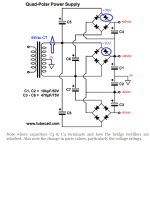
The AC from the center tapped transformer goes to the middle bridge, making a dual supply (+ and - 30V at C1 and C2). This is a common supply for SS designs, where a symmetric +- supply is needed. Note the cap C5-C8. These form a "short circuit" for AC, so the AC provided to the middle bridge is also supplied to the upper and lower bridge. There are filtering caps attached to these bridges as well (C4 at top, C3 at the bottom). These supplies are not floating however, but attached in series to C1 and C2, to create the multiple PS values.
So, why do we need C5-C8, or, why can't we just connect the three bridges in parallel, have a filter cap at each output, and then stack the outputs? Because there would be no potential difference between them. The C5-C8 allow a DC potential to be developed between the bridges (therefore called level shifters, because they shift the DC level). But at doing this a DC voltage develops over the caps, so the caps must be rated for that voltage.
I put some additional values in the schematic from Tubecad. With this schematic, when the AC sine coming from the transformer goes up, the two diodes in the blue circle conduct. One feeds the +30V, the other the +90V. Look at C5, it has the +30V at the negative connection, and the +90V at the positive, so it has a continuous 60V over it, which should be the minimum DC rating of this cap.
Furthermore, the caps are not complete short circuits, but they present a reactance (frequency based resistance). Just used a calculator to calculate that the reactance of a 100uF cap at the European 50Hz is about 31 ohms. For an auxiliary supply of some mA this is not a problem, but one must be aware of it. Using a 1uF cap would increase the reactance to 3100ohms. This cap is also called a wattless dropper, it is used a lot in cheap LED lamps, to reduce the 230VAC supply to something closer to what the LEDs need for proper working.
I do not think this explains the thing much better, I had to spend a lot of pen and paper and tutorials to get it. But I agree with the others, that in the supply that you show the caps are polarized wrongly. I don't know why did not explode yet.. as a filter cap in a PS a polarized cap connected wrongly will let so much current through that it overheats and explodes. In your case they are connected as level shifters, does this somehow limit the current through them??
Attachments
Nor do I. They are not even bulging.I don't know why did not explode yet
- Home
- Amplifiers
- Power Supplies
- What is the purpose of supplying the AC to rectifier through capacitors