Interesting additions to TPC.
What about settling time compared to simple TPC ?
Hans
Hi Hans,
I am not sure how simulate settling time, attached LTspice file of one of my built by quite a number of DIYers here.
BR Damir
Attachments
I usually check settling time in the simulator by feeding a fast rise-time square wave into the amp (1- 10 ns) with an 8 ohm resistive load. In many cases you will get overshoot, but it should settle quickly ie minimal or no ringing. When I do this test, I disconnect the input bandwidth limiting filter which I usually set to between 300 and 500 kHz (also acts as a RF filter).
If you then feed a normal music signal rise time in - say 5-10 us, there should be no overshoot (also with the RC filter disconnected).
Note the RC input filter is part of the compensation scheme IMV.
For practical testing, I use a function generator with a c. 100 ns rise time.
All test voltages BTW about 2V pk -pk.
Hans, how are you doing it? Maybe there are better techniques.
Last edited:
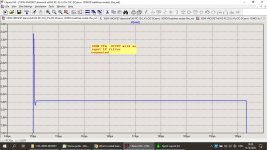
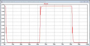
This is what I got on the amp I attached .asc file some post before.
If you feed a 5-10uS rise time signal in I don't think you will get overshoot, or very little. If you do, you could just lower the cut off frequency of the input filter a bit.
If you feed a 5-10uS rise time signal in I don't think you will get overshoot, or very little. If you do, you could just lower the cut off frequency of the input filter a bit.
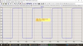
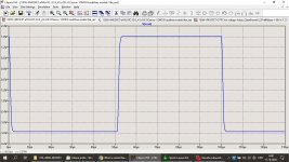
I use input LP filter with 220R/680pF and no overshoot, see second plot.
First one is with no input filter cap connected and 10nS rise-time square wave.
Hi Hans,
I am not sure how simulate settling time, attached LTspice file of one of my built by quite a number of DIYers here.
BR Damir
Hi Damir,
Could you also supply me with your dadomodels.txt library to run your amp.
Thanks in advance.
Hans
Hi Damir,
Could you also supply me with your dadomodels.txt library to run your amp.
Thanks in advance.
Hans
Yes, of course Hans, it's here.
")
Attachments
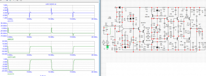
Andrew, I offer a square wave through a 150Khz first order filter.Hans, how are you doing it? Maybe there are better techniques.
Divide the output V(ls) by the gain and compensate for the time delay.
Then V(error)= V(ls)/gain -(V(in)-delay)
In LTspice I watch the signal at what point V(error) has settled to within 0.1%.
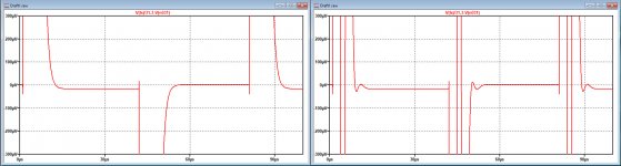
See here as an example of the amp that profdc9 presented.
Simulating single pole vs. Transistional Miller Compensation (TMC)
Single pole against TPC, where there was in this case no sign of a longer settling time, but only of a more violent coming to within 0.3mV or 0.1%.
So let's see what Damir's amp is doing.
Hans
Attachments
Damir,
Thank you for the text files.
When offering a +/-0.1V square wave signal with 1usec flanks at the input, I get a weird output signal with the model as supplied by you.
Connecting the signal ground to ground does not change anything.
What am I doing wrong.
The voltage and current sources for measuring the loop gain are switched off.
Hans
Attachments
Damir,
Thank you for the text files.
When offering a +/-0.1V square wave signal with 1usec flanks at the input, I get a weird output signal with the model as supplied by you.
Connecting the signal ground to ground does not change anything.
What am I doing wrong.
The voltage and current sources for measuring the loop gain are switched off.
Hans
Hi Hans,
I don't have that. Attached .asc file again, just run it and I suppose you will get the plot as attached too.
Damir
Attachments
I posted my answer in the wrong thread, here is the link
OITPC - Output inclusive TPC (not TMC)
Hans
OITPC - Output inclusive TPC (not TMC)
Hans
- Status
- This old topic is closed. If you want to reopen this topic, contact a moderator using the "Report Post" button.
- Home
- Amplifiers
- Solid State
- What is nested feedback, how it realy works and some examples...