Maybe it's not the best bedtime reading (or maybe it was the spicy BBQ
late at night) but as I was reading "Beam Power Tubes" by O.H. Schade
and contemplating the Eimac 4-65A tetrodes lying in a pile of wood
shavings on the workbench, I sketched a tetrode with plate feedback
and a high impedance triode as the lower leg of the grid divider and
called it a night. What a silly way to use a triode, I thought. And I want
grid current...
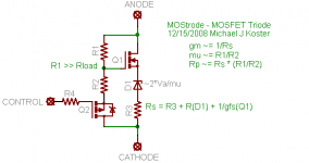
Well, by morning the triode had morphed into a pentode, then into a
MOSFET, then the tetrode itself morphed into a MOSFET, with the
following connections.
If feedback can turn a pentode into a linear triode, why not start
with a MOSFET?
I think the basic relationships are similar to what Schade describes
but I make some simplifying assumptions below. I also left out some
protection diodes. Probably some errors also... But in the context of
plate feedback discussions elsewhere I thought it would be of interest.
Cheers,
Michael
late at night) but as I was reading "Beam Power Tubes" by O.H. Schade
and contemplating the Eimac 4-65A tetrodes lying in a pile of wood
shavings on the workbench, I sketched a tetrode with plate feedback
and a high impedance triode as the lower leg of the grid divider and
called it a night. What a silly way to use a triode, I thought. And I want
grid current...
Well, by morning the triode had morphed into a pentode, then into a
MOSFET, then the tetrode itself morphed into a MOSFET, with the
following connections.
If feedback can turn a pentode into a linear triode, why not start
with a MOSFET?
I think the basic relationships are similar to what Schade describes
but I make some simplifying assumptions below. I also left out some
protection diodes. Probably some errors also... But in the context of
plate feedback discussions elsewhere I thought it would be of interest.
Cheers,
Michael
Attachments
- You are only now discovering this?
I guess...
Thought it would be fun to play with and build a one-stage SE'T'
amplifier with only local feedback. The idea is to use it as a triode
in-circuit.
Do you have a reference for prior work? I couldn't find anything on
a quick search.
Michael
I guess...
Thought it would be fun to play with and build a one-stage SE'T'
amplifier with only local feedback. The idea is to use it as a triode
in-circuit.
Do you have a reference for prior work? I couldn't find anything on
a quick search.
Michael
I wondered if this was the same Schade who did the classic work on rectifiers and it was. Schades curves avaliable here page 118 onwards Also an example of Power supply design for an audio amplifier page 126
http://www.ieeta.pt/~alex/docs/ApplicationNotes/Rectifier Applications Handbook.pdf
http://www.ieeta.pt/~alex/docs/ApplicationNotes/Rectifier Applications Handbook.pdf
Hi Michael,
I think that circuit is pretty much what Ken was calling a Fetron or Fetrode. I think he said he found it somewhere else too. There was an article in Electronics World some time back on making a SS sub for tubes, not sure if that would be the original.
OT:
ever get any info from Bob Carver on his mysterious 6AL5 DC restorer?
Don
If nothing else, Nelson Pass' "Zen" is the same basic circuit.
And his slightly overcomplicated "Aleph" current source an
Anti-Triode (or Anti-Fetron)...
I doubt Nelson designed either with any regard toward Triode
or Anti-Triode emulations. Its still a good circuit, no matter what
angle of sandy or hollow state thinking brings one around to it.
More than once I've posted P-Channel Fetrons for discussion.
Seeing no need to offend the glass world with a redundant N-
Channel competitor.
And the same circuit bent around a GTBT as a potential stand-
alone emulator for an Anti-Triode (not requiring a reference).
And another nutty idea gone entirely wrong...
I think my intention was P-Fetron on the left side,
and Brute bridged P-Antifetron on the right side?
Abuse a bifilar dual voice coil sub as a very low
impedance PP transformer to directly drive a full
range loudspeaker in tandem.
Or maybe the driver side was the P-AntiFetron?
And the passenger side then P-AntiAnti? I forget
now what bizarre point I was trying to prove by
this exercise???
------------------------------------------
Anyways, the point I'm trying to make here today:
That they all share a simplified version of Schade's
local feedback scheme. A resistive divider repairing
the "broken triode" hidden in Tetrodes, Pentodes,
and certain sandy devices.
Attachments
Hi Ken,
I just returned from a similar archaeology expedition, and found
indeed a number of your fetron references wrt. O.H. Schade, which
is apparently what I just recreated. Now I know what you were
talking about all this time!
I'm a little curious why emulating 3/2 power is important. What's
wrong with a device that has more constant mu and Rp over it's
op range?
I didn't call it a fetrode because that's a registered trademark
of a biosensor company.
So at least it looks like I've distilled it down to a few parts with a
simple explanation ;-) I think it can make a practical one-element
amplifier with a nice triode characteristic, as well as a teaching tool
about triodes and pentodes for people raised on solid state...
Also this simplified circuit can be directly mirrored to P-version,
with an n-buffer and p-gain element.
I'm expecting my plate curves to look a little different, though...
more like DHTs; very linear down to the bias current baseline.
I think I'll at least try to get some curves from an actual circuit here.
Cheers,
Michael
Don
- ever get any info from Bob Carver on his mysterious 6AL5 DC restorer?
First, an interesting assertion that trying to negative peak detect
the common cathode current would fail because of common mode
current. (I actually did have a problem with a positive feedback of
some kind that appeared to be related to common mode current)
I wonder if he follows these groups...
He didn't elaborate further except to say that balance control
wasn't as important as bias stability was, that anything with a time
constant has a negative impact on music, that sampling schemes
aren't reliable and don't account for drift, and that his scheme
continuously corrects zero-signal current without a time constant.
Apparently *not* by negative peak detecting cathode current minima.
So what could a vacuum diode do uniquely to this end?
I should try again to follow up but have been working on other
pursuits. I do agree with avoiding sampling and time constants and
also think continuous correction is possible. Maybe as I get more
interested in class AB operation I'll look into it again.
Michael
PS FETRON may not be a current trademark, but was apparently
used by Teledyne (an ex-employer of mine) as a trade name for
a solid state FET based replacement for vacuum tubes. They were
used in telephone equipment and found some use in guitar amps
(Mesa Boogie). They were packaged in 9-pin and TO-3 like cans.
So FETRODE and FETRON are already well known names for other
devices (though the FETRON is a similar use, it was a high voltage
depletion mode FET, not a Schade application of local feedback).
So I'll stick with MOStrode for now. I can only find MOST RODE
motorcycles...
Attachments
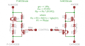
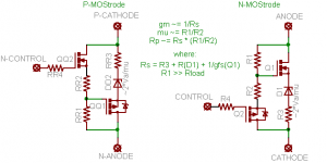
Dude, your P version may be a little messed up?
You can't get to P by just changing MOS channel
arrows, whole entire topology has to be flipped.
A proper P-Gate always differs toward the source
of imaginary hole carriers. Up towards P-Anode.
Just as an N-Gate must always differ toward the
source of electrons coming from the N-Cathode.
You can't get to P by just changing MOS channel
arrows, whole entire topology has to be flipped.
A proper P-Gate always differs toward the source
of imaginary hole carriers. Up towards P-Anode.
Just as an N-Gate must always differ toward the
source of electrons coming from the N-Cathode.
Michael
re: B.Carver and 6AL5
Only thing I can think of that would not have a time constant would be to put the 6AL5 diodes parallel with a cathode resistor to act as a non-linear zener. Sort of like P. Turners scheme:
http://www.turneraudio.com.au/schem-300w-5-bias-stabilizer.html The diode only significantly activating on class B peaks. A 6JU8 would give more diodes to series or parallel than the 6AL5.
Would be more conveniently programmable if a Mosfet could be included or used instead.
Plan B:
The classical DC restorer circuit is just a coupling cap into a diode to ground, so that the output side is locked to ground on one polarity of peaks. But the cap would seem to introduce a time constant somewhere when source impedance and load impedance are considered.
But, ignoring the time constant issue, there may be a clever scheme available here. Suppose the diode's cathode is connected to the tube's grid and the diode's anode connected to the bottom of the tube's autobiasing cathode resistor. Sorta the opposite of blocking distortion. Idea would be to set the grid bias (held on the grid coupling cap) so that signal peaks determine the bias.
Or something like that. I'm still confused about what its even supposed to do.
Don
Looks like Plan B just nulls out DC blocking distortion for an auto biased stage. (by symmetrically conducting at both signal peaks, g1 conduction on pos. pks and 6AL5 diode conduction on neg. pks) I guess thats useful. And looks like no time constant since the bias is staying steady. Probably needs a high value grid resistor from the bottom of the cathode resistor to the grid to get things initialized.
I suppose one could tap the cathode resistor for the 6AL5 diode anode connection to get a varying bias for class B extension. With the additional high value resistor from the bottom of the cathode resistor to the grid to set normal bias. Then bias decreases during class B periods due to the 6AL5. But the R and coupling C would have a time constant for bias settling back to normal.
Sorry for going off topic. If this 6AL5 bias stuff looks like its on track, maybe we should make a new thread. I'm not sure if this is Carver's scheme though. But seems useful.
Don
OOps. On the Plan B thing, looks like the cathode resistor needs to be twice the normal value, with the grid bias resistor connected half way, ie centered (for normal auto bias), and the 6AL5 diode anode connected to the bottom of the doubled cathode resistor. That way the g1 conduction (from blocking dist.) and the 6AL5 conduction are symmetrical for preserving the auto bias. A big cap can be put across the whole cathode resistor to prevent degeneration, like normal auto bias.
Attachments
"I'm not buying it. We are forgetting the tube amplifies
and the diode does not. The currents can not be equal."
Well, the Rk1 and Rk2 resistors could be made unequal and/or the 6AL5 could have multiple sections in parallel. (6JU8 has 4 sections available) Just signal test with the given tube and tweak these until g1 bias stays stable with a large signal input.
Don
With all separate diodes, they could be separately tapped on the Rk resistor stack to form a diode function generator effectively --- just in case the g1-k "diode" doesn't conform to normal diode conduction rules. We've probably improved on Carver's design now. Wonder if he checks this forum.
edit,
Um..., 4 diodes, 8 leads plus 2 leads for the heater, that's not adding up to nine pins. Looks like the 6JU8 has two sets of series connected diodes. Well, we may have to use 6AL5s then. Although series diodes could be useful for lowering the conduction of a section as part of a diode function generator string.
Let's see, there is the 6AN6 too. Has a common cathode and 4 separated anodes. That's fine actually, since the anodes would be connected to the Rk taps.
smoking-amp said:With all separate diodes, they could be separately tapped on the Rk resistor stack to form a diode function generator effectively --- just in case the g1-k "diode" doesn't conform to normal diode conduction rules. We've probably improved on Carver's design now. Wonder if he checks this forum.
...
Interesting this keeps happening. I looked in my notebook about 2
weeks back and there is the 2nd stage of my micpre design with
a 437A and a diode and resistor network to balance grid current
when the grid swings negative, and a note about multiple parallel
strings to approximate the nonlinear grid resistance. Tune the
diode and R drops to get the hockey stick grid current curve.
I wanted to try this to improve the usable dynamic range of the
preamp by avoiding blocking (The 437A and 417A both like a little
grid current IME).
I'm still not visualizing what this does in class AB push-pull and
how it stabilizes bias. I guess I need to re-read your posts and
think it through. Something I'm missing. I'm certainly willing to
try it on a class AB2 thing I'm planning that sounds like a good
candidate.
Michael
kenpeter said:Dude, your P version may be a little messed up?
You can't get to P by just changing MOS channel
arrows, whole entire topology has to be flipped.
A proper P-Gate always differs toward the source
of imaginary hole carriers. Up towards P-Anode.
Just as an N-Gate must always differ toward the
source of electrons coming from the N-Cathode.
I'm not sure I follow but you seem to be saying that I have the
semantics of a P-tube wrong and the control signal should reference
the P-anode, but that's why I call it a P-cathode; because it is the
origin of the imaginary p-hole space charge. Or positron space charge...
So it looks like my original P-MOStrode got everything backwards
except the zener diode

Michael
Attachments
- Status
- This old topic is closed. If you want to reopen this topic, contact a moderator using the "Report Post" button.
- Home
- Amplifiers
- Tubes / Valves
- What if O.H. Schade had MOSFETs?