Sorry for my comment ")
I have no experience with gainclones (but I built many amps using ICs). The fuse in the rail or transformer is to protect the components from high current draw. Using a small wattage chip (usually class B) how much current do you expect? I don't think that a fuse is needed at all.
In some circuits the required rating depends on the maximum expected current drawn. That will be dependent upon the design of the circuit.
thanks for the replys.
My transformer is a 225VA 2x25V, I forgot to mention that in the first post.
It seems that from the posts so far that to find the correct fuse value you just start at a small value and work your way up untill you get a fuse value that dosent blow. and the fuse should be the slow blow types as well i would guess.
thanks
Kram
Peter, I think if we connected the transformer to power line with no load, there would be virtually no current, unless there was something wrong with the transformer. In a small amplifier, what would be the cause of high current inrush? Shorted 12V-12V? May be I have just been lucky, never used any fuse in the primary (230V) and never got a problem 
Kram, you sure won’t put the fuse on the DC rail. May be on the primary winding of the transformer as Peter suggested, which I doubt it’s effectiveness. But if the winding you are trying to protect, you don’t have to “experiment” like that with the fuse value. And use a fast blow.
The 25V goes to diodes, from the diodes straight to the chip with one or two caps for each DC rail right? Is gainclone a name of a circuit?
Basic electrical rules dictates that a fuse protects everything that is "upstream" from the fuse from any short or overload that occurs "downstream" from the fuse. So a fuse at the primary of the x-former may not save this x-former's primary if the bridge shorts, especially so, if the fuse is a slow blow type. Remember that such a fuse works under the I^2R logic, which in practical terms says that it will blow after the short term current passing through it exceeds the 10X of whatever current value is written on the body of the fuse. Thus my opinion is never use a slow blow fuse when you are testing a circuit. You may do it for well behaving and trusted circuits, but even then with caution.
Laminated toroid x-formers draw much more inrush current from the utility plug compared to the laminated E-I or C x-formers, due to the luck of a gap at their magnetic circuit. The current drawn to charge the initially uncharged capacitors saturates the core. During saturation, the core's permeability falls to almost 1, so the inductance of the primary winding falls rapidly, leading to an increase of the primary winding's current.
This doesn't happen when the x-former secondary is not connected to anything (unloaded), as then, only the "magnetising current" which is really low, is drawn.
Regards
George
gpapag said:Basic electrical rules dictates that a fuse protects everything that is "upstream" from the fuse from any short or overload that occurs "downstream" from the fuse. So a fuse at the primary of the x-former may not save this x-former's primary if the bridge shorts, especially so, if the fuse is a slow blow type. Remember that such a fuse works under the I^2R logic, which in practical terms says that it will blow after the short term current passing through it exceeds the 10X of whatever current value is written on the body of the fuse. Thus my opinion is never use a slow blow fuse when you are testing a circuit. You may do it for well behaving and trusted circuits, but even then with caution.
Laminated toroid x-formers draw much more inrush current from the utility plug compared to the laminated E-I or C x-formers, due to the luck of a gap at their magnetic circuit. The current drawn to charge the initially uncharged capacitors saturates the core. During saturation, the core's permeability falls to almost 1, so the inductance of the primary winding falls rapidly, leading to an increase of the primary winding's current.
This doesn't happen when the x-former secondary is not connected to anything (unloaded), as then, only the "magnetising current" which is really low, is drawn.
Regards
George
A primary fuse will work very good to save the transformer if the bridge shorts. Even a slow fuse will be slower than the transformer. Having the fuse in the secondary of the transformer won't make much difference except from the different value, and that it wouldn't prevent a meltdown if the transformer shorts.
That transformers would saturate from high secondary current is a very common misconception. Transformers doesn't saturate from too high secondary loading. High secondary loading actually makes the opposite happen because of the voltage drop over the primary resistance. The start-up surge is of course bigger with capacitors connected because they have to be charged, but even a transformer without capacitor loading usually has high startup surge.
In steady-state operation the flux is at its peak negative value when the voltage crosses from negative to positive. The first part of the next half cycle will bring the flux up to zero, and the second part will bring it to its peak positive value, which will be reached at the zero crossing.
If the transformer is turned on at a zero crossing the flux will be around zero, and the *whole* half cycle will then build up the flux in the same direction. This makes the flux do a twice as big excursion which very probably will drive the core into saturation. This will after a short while even out because of assymetric voltage drop over the primary resistance.
(I hope this was clear, I'm not very good at expressing myself in English i beleive
)Since we are talking about safety devices (fuses), i think that i should be a bit more specific:
refers to its rated current carrying capacity, not to its breaking capacity.
The cut-off current (breaking capacity) is determined by the I^2t integrated up to the moment of melting.
From published curves one can see that depending on the fuse type, the ratio of cut-off current to current rating, is from 3 to 1 (fast fuses) to 10 to 1 (slow fuses). Furthermore, for each specific fuse type, this ratio is not fixed, but varies in respect to time t.
Some things are quite "dry" and maybe boring too, but so is the "safety" issue itself.
Regards
George
I myself use only one fuse at the primary and not two fuses, one at the primary and one at the secondary. I do this for reasons of lay-out simplicity. Actually it is wrong and i have already paid the price more than once during experimentations. The fact is that the fuse at the secondary saves the x-former from shorts occuring downstream (bridge, caps...), while a fuse at the primary is intended to isolate the xformer from mains if an overcurrent occurs at the primary. The fuse at the primary MAY save the transformer if the bridge shorts, but nobody should make a definite statement about it.So a fuse at the primary of the x-former may not save this x-former's primary if the bridge shorts, especially so, if the fuse is a slow blow type
I appologise. I should have typed I^2t instead. This is a short expression of the time integral of the I^2 dt (the Joule integral)Remember that such a fuse works under the I^2R logic...
The current rating of a fuse (the current value written on the fuse)...which in practical terms says that it will blow after the short term current passing through it exceeds the 10X of whatever current value is written on the body of the fuse
refers to its rated current carrying capacity, not to its breaking capacity.
The cut-off current (breaking capacity) is determined by the I^2t integrated up to the moment of melting.
From published curves one can see that depending on the fuse type, the ratio of cut-off current to current rating, is from 3 to 1 (fast fuses) to 10 to 1 (slow fuses). Furthermore, for each specific fuse type, this ratio is not fixed, but varies in respect to time t.
Some things are quite "dry" and maybe boring too, but so is the "safety" issue itself.
Regards
George
Hi megajockeThat transformers would saturate from high secondary current is a very common misconception
You are right on this. High (steady state) secondary current does not saturate the core. I wasn't meaning that though. I wrote "The current drawn to charge the initially uncharged capacitors saturates the core". And this is how i understand this:
The initial charging implies a high rate of change of secondary current from a low value to a high one. This momentarilly forces a flux in the core with opposite direction to the flux produced by the primary winding. The resultant flux momentarilly then is much less than the steady-state one. So is the primary's inductance. Inductance being low, drives primary current high. This high current is destined to increase the primary's EMF in order to reach the (opposite) value of the applied (mains) voltage and to momentarily increase again the (by the primary produced) magnetic flux in the core in order to preserve the equilibrium. At this moment the core can saturate.
In this whole story (which is oversimplified, because interaction between primary and secondary produce more changes than these described) we have an one time increase of the primary current due to low primary inductance, then a decrease, then an increase again because of the core's saturation. The phenomenon tends to self ballance after this (damped oscillation actually). Observe the flickering on the intensity of the rooms electric lighting when you switch on a heavilly loaded torroidal x-former. This phenomenon reduces or is eliminated when the inductance of the primary is quite high from the beginning (more turns per volt).
The same thing seems to happens (but less pronounced) in every capacitor's charging cycle. Remedy is the same (primary's more turns per volt) and/or some small resistor between bridge and capacitor.
Regards
George
gpapag said:
Hi megajocke
You are right on this. High (steady state) secondary current does not saturate the core. I wasn't meaning that though. I wrote "The current drawn to charge the initially uncharged capacitors saturates the core". And this is how i understand this:
The initial charging implies a high rate of change of secondary current from a low value to a high one. This momentarilly forces a flux in the core with opposite direction to the flux produced by the primary winding. The resultant flux momentarilly then is much less than the steady-state one. So is the primary's inductance. Inductance being low, drives primary current high. This high current is destined to increase the primary's EMF in order to reach the (opposite) value of the applied (mains) voltage and to momentarily increase again the (by the primary produced) magnetic flux in the core in order to preserve the equilibrium. At this moment the core can saturate.
In this whole story (which is oversimplified, because interaction between primary and secondary produce more changes than these described) we have an one time increase of the primary current due to low primary inductance, then a decrease, then an increase again because of the core's saturation. The phenomenon tends to self ballance after this (damped oscillation actually). Observe the flickering on the intensity of the rooms electric lighting when you switch on a heavilly loaded torroidal x-former. This phenomenon reduces or is eliminated when the inductance of the primary is quite high from the beginning (more turns per volt).
The same thing seems to happens (but less pronounced) in every capacitor's charging cycle. Remedy is the same (primary's more turns per volt) and/or some small resistor between bridge and capacitor.
Regards
George
Ok. Maybe that's right, but I don't know. Can current really increase faster in the secondary than the primary? Where does that current come from then?
Just use a slow fuse
A fast fuse with a capacitor-loaded transformer would have to be to large to be useful. You could use fast fuses after your filter capacitors to protect the amp.An even more basic use
The fuse in the primary protects your house! It is entirely possible that your amp may draw enough to heat up to the point it starts a fire, but not enough that it trips the breaker for the mains. It seems very foolish to not put a cheap part into the primary wiring that provides this protection. I have doubts that even the most golden ears could hear this fuse.
The value of the fuse should be enough to handle the inrush x say 150%. After some years, it is likely that this fuse will blow from stress and age. But that will be after many years of basic protection.
Hi megajockeCan current really increase faster in the secondary than the primary? Where does that current come from then?
Secondary current can increase fast, and this rate of change (not only the actual value) MAY produce all the problems. There is no perpetual mechanism there. Secondary current demand has to be supported by an appropriate magnetic flux in the core which has to be produced by the primary winding.
SawzallThe fuse in the primary protects your house!
You are absolutely right! The fuse at the primary is concindered by me to be mandatory, because is the safety device at the connection between the equipment and the mains. The fuse at the secondary is not a safety device. It is an internal component's (x-former) protective device. Under this context, i don't understand how most of the manufacturers of small power equipment (tuners, CDR) do not use a fuse upstream of the x-former anymore, but only fusible devices downstram of the x-former instead. This can be partially acceptable in U.K. where wall outlets incorporate a fuse, but not elsewhere where the fuses /circuit brakers are located far away in distribution panels.
Regards
George
gpapag said:
Hi megajocke
Secondary current can increase fast, and this rate of change (not only the actual value) MAY produce all the problems. There is no perpetual mechanism there. Secondary current demand has to be supported by an appropriate magnetic flux in the core which has to be produced by the primary winding.
But flux is proportional to current. Not the rate of change of the current?
Sawzall
You are absolutely right! The fuse at the primary is concindered by me to be mandatory, because is the safety device at the connection between the equipment and the mains. The fuse at the secondary is not a safety device. It is an internal component's (x-former) protective device. Under this context, i don't understand how most of the manufacturers of small power equipment (tuners, CDR) do not use a fuse upstream of the x-former anymore, but only fusible devices downstram of the x-former instead. This can be partially acceptable in U.K. where wall outlets incorporate a fuse, but not elsewhere where the fuses /circuit brakers are located far away in distribution panels.
Regards
George
There might be a thermal fuse inside. Or maybe they assume that their components are perfect and never fail
But what difference does the distance to the fuses make? UK plugs have 13A fuses don't they? Here in Sweden our circuits are almost always fused at the central with 10A fuses or circuit breakers. But maybe those are slower than the ceramic 5x20mm fuses in UK plugs. I would never build anything without a primary fuse.Fuses
Look, there's some basic physics that we can use here. Power = Current times Voltage. P=VI. Now, if your transformer is rated at 225 VA (or 225 Watts, as we physicists would call them,) and your line voltage is 240, then the working limit for your transformer should be 225 W/240V = 0.9375 Amps. So a 1 amp fuse will let you run about 8% over spec before blowing, and you will need to use a slow-blow to
prevent the initial turn-on inrush from blowing it immediately.
Mind you, this is just a starting point.
Finally, the purpose of the fuse is to , protect your house, lab, or wherever, in the event of a short anywhere in the system. If the bridge fails, the transformer fails, or any other part draws huge currents, the fuse will blow to prevent a fire. If it saves any other components, that's a bonus.
Regards,
aeronaut
from Peter Daniel My 400VA toroid powered by 120V line was blowing 2.5A fuses, because of a big inrush current at turning on.
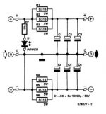
Kram : Here's a newbie "quick and dirty" solution to prevent fuse blowing up on power up.
There's more advanced circuits using relays but if you've got problems with fuse blown by inrush current, this should do the trick. Oh, by the way, don't use LEDS as shown on the schematic !
Attachments
I hope so because thats what ive just orderd. RS part no. 416-512
Oh no! The Farnells ones sound a lot better

(Sorry Kram - couldn't resist it)
- Status
- This old topic is closed. If you want to reopen this topic, contact a moderator using the "Report Post" button.
- Home
- Amplifiers
- Chip Amps
- what fuse for gainclone