Hi Kanwar,
Yes driving these individually in a voltage gain stage to minimize losses is the way to go to max the power efficiency.
A word of caution - although the SOAR is awesome and the devices are no doubt very rugged, the duration is very small and the case is 25C. You admit to 50C days before the amp is powered up! What's the 1 second curve - same derating as the previous two?
Set up in an amplifier at 80V rails the pkg allows about 5A at zero crossing . That's at case of 25C and continuous. You're opting for 75C and the pulsed region to drive reactive loads. I usually design for driving an 8 ohm load of any phase angle. Then -
Supply Voltage/8 = 10 amps so it should be capable of 10 amps at zero crossing. Therefore 2 devices per half (2 upper/2 lower)
But, hey, you have a shipload of them and are extracting more so good for you if their that rugged and reliable.
For a Hi End amp you would want to lower the THD at 20KHz significantly and that would be quite difficult with such slow devices. Good for Workhorse PA though. For better sound you could biamp with a smaller more agile refined amp for the top.
Duh...indeed... 
Place your mouse cursor directly above this:
http://www.diyaudio.com/forums/showthread.php?postid=585564#post585564
...and Left-click!!
Place your mouse cursor directly above this:
http://www.diyaudio.com/forums/showthread.php?postid=585564#post585564
...and Left-click!!
How not to communicate in English.
Mikeks,
When I open the link AND expand it to full screen there are 3 posts none bearing any reference numbers 585564, so to which one specifically are you referring and why?
I have no idea as all you posted was a link . In response to what?
Mikeks,
When I open the link AND expand it to full screen there are 3 posts none bearing any reference numbers 585564, so to which one specifically are you referring and why?
I have no idea as all you posted was a link . In response to what?
guru,
#whatever in a URL means that "whatever" is the name of a tag in the HTML source. It's simply used as a reference or bookmark of sorts for a position on a page. If you mouseover one of the "Post #foo" links in the top right of any thread post, you will see something like the #post585564 which simply means scroll down to the tag named "post585564" on the page mikeks linked to. So click his link, and whatever is at the top is whatever he wanted to share.
#whatever in a URL means that "whatever" is the name of a tag in the HTML source. It's simply used as a reference or bookmark of sorts for a position on a page. If you mouseover one of the "Post #foo" links in the top right of any thread post, you will see something like the #post585564 which simply means scroll down to the tag named "post585564" on the page mikeks linked to. So click his link, and whatever is at the top is whatever he wanted to share.
Hi, Kanwar,
I also seduced by using only 1 big transistor instead of parrarel smaller ones. A commercial amp (Gamut) has also use this idea.
But since those big transistors usually are Nch, this will direct us to quasi complementary topology. Do you also use this topology?
Gamut uses industrial mosfet. I haven't heard audio power amp using industrial IGBT (JLH uses audio IGBT/complementary N+P. The industrial IGBT modules are different nature and BIG SIZE indeed) Maybe your product will pioneer the use of it in audio amps?
How is the sound result? Is it different sound than using bipolar or mosfet?
I also seduced by using only 1 big transistor instead of parrarel smaller ones. A commercial amp (Gamut) has also use this idea.
But since those big transistors usually are Nch, this will direct us to quasi complementary topology. Do you also use this topology?
Gamut uses industrial mosfet. I haven't heard audio power amp using industrial IGBT (JLH uses audio IGBT/complementary N+P. The industrial IGBT modules are different nature and BIG SIZE indeed
) Maybe your product will pioneer the use of it in audio amps? How is the sound result? Is it different sound than using bipolar or mosfet?
I have seen IGBT's promoted for use in audiopower amplifiers several times, but not for very long. Like the Alexander Power Amplifier (Current Feedback design). Undoubtedly this amplifier is sounding very good, but when photos of melted down output transistors started to emerge, the interest in IGBT's tended to slightly cool down.
Now why are IGBT's vulnarable in audio amplifiers? Well the input MOSFET drives the Base of the BJT on, and that's all fine. However the base / collector capacitance is driven off only by a resistor between base and emitter. So it has no way of turning off fast when that is required, only the resistor will turn the base off. Which is no problem when you have a slow turn-off time requirement. (Like less than 20 kHz). But what happens when your amp gets the message to send out a 40 kHz signal? First cross conduction, and then shortly after ..... poof!
To make things worse as it happens, the base - collector capacitance is parallelled with the output capacitance of the driving MOSFET. I would never consider it safe to use any IGBT in an audio design. And not even worthwhile. OK you get the easy gate drive of the MOSFET, but you stil have to cope with second breakdown flaws of the BJT.
For large amplifiers better to use simply N-Ch MOSFET, they dont have second breakdown problems, they are cheap, small and very rugged.
About Gamut, as NP has pointed out earlier (to my own surprise) the 'single MOSFET output devices' turned out to contain 2 silicon crystals inside the box. (Again according to NP) And not necessarily from the same wafer. So that idea kind of went overboard ...
However IXYS and APT make nice big single chip power MOSFET's
that can safely produce > 1 kW of audio power a pair.
Hi, LC,
Nice to see you again
I learn an important message. Making a device "OFF" is the same importance as making it "ON". IGBT is inherently flaw for high frequencies, that's why I doesn't see very much of it.
Is it really worth the sound quality to make an amp with 1 mamoth device compared to parrareled smaller ones? Or is it more about durability?
Hi everyone
Hi guru,
you seems to me as very much interested in IGBT's
Since we employ dual side heatsinking and devices are mounted using bar clamping with nuts and bolts.
The mounting order is of type ------5mm thick Aluminium bar--> IGBT device --->8mm thick copper slab [3"X3"]--->10mm thick base aluminium heatsink. Nothing sort of insulators between devices and heatsink.
The one second curve is slightly lower than other 2 curves[obtained through special request from APT].
We have tested the amp with reactive energy discharge and found out that these monsters are really very rugged, nothing sort of damage is encountered during driving of highly reactive loads. Although we have plans to boost the output power of our module upto 1800W using 2 pairs in parallell in order to increase thermal safety in long run.
We doesnot have ship load of them , only 100 pieces each costing 12 dollars approximately.
This amp would be our HIgh power version of Workhorse STALLION series and its strictly meant for the hardcore PA use only. Since our another models are all N-channel VMOS types ,so nothing to worry for high-end HI-FI performance.
The distortion figure of IGBT amp are:
20Hz = 0.001%.....1KHz = 0.01%....25KHz = 0.05% at full rated power.
Hi lumanauW,
Our topology is quasi-complementary, but with individual push-pull drivers.
We Dont know whether we pioneer IGBT's in audio amps or not, but one thing is for sure that we want to become the first professional amp manufacturer in this world to implement N-channel IGBT in Professional amp for PA use.
The Sound is totally different from the mosfets and certainly from the bipolars. The main difference is of damping factor which is around 1000 in our case and thats true indeed.
Hi LARS CLAUSEN,
The ALEXANDER amp uses complementary IGBT's from TOSHIBA not the N-channel ones from the APT.
We have tested our amp upto 50KHz with no sign of cross-conduction, THANKS to our driver stage for efficient turn-OFF/ON characteristics.
Secondly regarding Second breakdown voltage in case of IGBT's from APT, our advise is that you must update your knowledge about the IGBT's from APT as they they have no second breakdown voltage phenomena in them.
Please visit this link www.advancedpower.com for more information on new generation of IGBT's which are positive temp. coefficient devices with no second breakdown voltage in their datasheets.
regarding mosfets , we are already using them in our amps upto 1200+1200Wrms ratings.
regards to all,
Kanwar
amplifierguru said:Hi Kanwar,
What's the 1 second curve - same derating as the previous two?
Set up in an amplifier at 80V rails the pkg allows about 5A at zero crossing . That's at case of 25C and continuous. You're opting for 75C and the pulsed region to drive reactive loads. I usually design for driving an 8 ohm load of any phase angle. Then -
Supply Voltage/8 = 10 amps so it should be capable of 10 amps at zero crossing. Therefore 2 devices per half (2 upper/2 lower)
But, hey, you have a shipload of them and are extracting more so good for you if their that rugged and reliable.
For a Hi End amp you would want to lower the THD at 20KHz significantly and that would be quite difficult with such slow devices. Good for Workhorse PA though. For better sound you could biamp with a smaller more agile refined amp for the top.
Hi guru,
you seems to me as very much interested in IGBT's
Since we employ dual side heatsinking and devices are mounted using bar clamping with nuts and bolts.
The mounting order is of type ------5mm thick Aluminium bar--> IGBT device --->8mm thick copper slab [3"X3"]--->10mm thick base aluminium heatsink. Nothing sort of insulators between devices and heatsink.
The one second curve is slightly lower than other 2 curves[obtained through special request from APT].
We have tested the amp with reactive energy discharge and found out that these monsters are really very rugged, nothing sort of damage is encountered during driving of highly reactive loads. Although we have plans to boost the output power of our module upto 1800W using 2 pairs in parallell in order to increase thermal safety in long run.
We doesnot have ship load of them , only 100 pieces each costing 12 dollars approximately.
This amp would be our HIgh power version of Workhorse STALLION series and its strictly meant for the hardcore PA use only. Since our another models are all N-channel VMOS types ,so nothing to worry for high-end HI-FI performance.
The distortion figure of IGBT amp are:
20Hz = 0.001%.....1KHz = 0.01%....25KHz = 0.05% at full rated power.
lumanauw said:Hi, Kanwar,
I also seduced by using only 1 big transistor instead of parrarel smaller ones. A commercial amp (Gamut) has also use this idea.
But since those big transistors usually are Nch, this will direct us to quasi complementary topology. Do you also use this topology?
Gamut uses industrial mosfet. I haven't heard audio power amp using industrial IGBT (JLH uses audio IGBT/complementary N+P. The industrial IGBT modules are different nature and BIG SIZE indeed
How is the sound result? Is it different sound than using bipolar or mosfet?
Hi lumanauW,
Our topology is quasi-complementary, but with individual push-pull drivers.
We Dont know whether we pioneer IGBT's in audio amps or not, but one thing is for sure that we want to become the first professional amp manufacturer in this world to implement N-channel IGBT in Professional amp for PA use.
The Sound is totally different from the mosfets and certainly from the bipolars. The main difference is of damping factor which is around 1000 in our case and thats true indeed.
Lars Clausen said:I have seen IGBT's promoted for use in audiopower amplifiers several times, but not for very long. Like the Alexander Power Amplifier (Current Feedback design). Undoubtedly this amplifier is sounding very good, but when photos of melted down output transistors started to emerge, the interest in IGBT's tended to slightly cool down.
Now why are IGBT's vulnarable in audio amplifiers? Well the input MOSFET drives the Base of the BJT on, and that's all fine. However the base / collector capacitance is driven off only by a resistor between base and emitter. So it has no way of turning off fast when that is required, only the resistor will turn the base off. Which is no problem when you have a slow turn-off time requirement. (Like less than 20 kHz). But what happens when your amp gets the message to send out a 40 kHz signal? First cross conduction, and then shortly after ..... poof!
To make things worse as it happens, the base - collector capacitance is parallelled with the output capacitance of the driving MOSFET. I would never consider it safe to use any IGBT in an audio design. And not even worthwhile. OK you get the easy gate drive of the MOSFET, but you stil have to cope with second breakdown flaws of the BJT.
For large amplifiers better to use simply N-Ch MOSFET, they dont have second breakdown problems, they are cheap, small and very rugged.
Hi LARS CLAUSEN,
The ALEXANDER amp uses complementary IGBT's from TOSHIBA not the N-channel ones from the APT.
We have tested our amp upto 50KHz with no sign of cross-conduction, THANKS to our driver stage for efficient turn-OFF/ON characteristics.
Secondly regarding Second breakdown voltage in case of IGBT's from APT, our advise is that you must update your knowledge about the IGBT's from APT as they they have no second breakdown voltage phenomena in them.
Please visit this link www.advancedpower.com for more information on new generation of IGBT's which are positive temp. coefficient devices with no second breakdown voltage in their datasheets.
regarding mosfets , we are already using them in our amps upto 1200+1200Wrms ratings.
regards to all,
Kanwar
Dear Kanwar
I noticed the lack of second break down in the APT devices. However my remarks were more a general point of view. I think it is safe to say that BJT's (and IGBT's) in general have a second breakdown region. Which causes a mpre or less significant reduction in the current performance.
The real problem of IGBT's is still the turn off delay however. And i would guess also the price per dissipated W .. ? This is just a guess however. Just for fun i checked out your device from APT. Turn on 38 nS, turn off 230 nS. Enough for me to render it unsafe for full range audio. Maybe ok for a bass-only amp though
The benefits on the other hand are more difficult to spot.
You can dissipate 295W at 20 deg C in your IGBT.
In a MOSFET also from APT like the APT50M65LLL (same case)
you can dissipate 590W. Exactly twice.
And in that one both turn on and turn off delays are around 30 nS. Now that's what i call a stable and reliable output device.
But maybe the IGBT's are cheap ????? (Question)
Hi
Hi lars,
Thanks for updating your knowledge. The devices from APT doesnot suffer from second breakdown voltage.
The device may be rendered unsafe for audio according to you, but only in audiophile quality Hi-Fi, because our amp is delivering 50KHz of clean sinewave with no sign of cross-conduction at full power there fore it can be very well implemented in professional audio amps. Meanwhile the switching times of IGBT are still lower than corresponding bipolars used in pro-amps.
We have also used APT20M18LVR , a 200V 100A Mosfet[16US$] with dissipiation of 625 watts @ 25.C which at 65.C temp its only capable of 275W . Whereas the APT100GF60LR [14US$]is rated at 300W @ 25.C , which still has 200W @65.C of dissipiation.Thats because of PLANAR CELL TECHNOLOGY which increase the power density and high temperature operation.
Secondly, We also use 20 X IRFP260N mosfets in our 2400W amp.
regards,
Kanwar
Lars Clausen said:Dear Kanwar
I noticed the lack of second break down in the APT devices. However my remarks were more a general point of view. I think it is safe to say that BJT's (and IGBT's) in general have a second breakdown region. Which causes a mpre or less significant reduction in the current performance.
The real problem of IGBT's is still the turn off delay however. And i would guess also the price per dissipated W .. ? This is just a guess however. Just for fun i checked out your device from APT. Turn on 38 nS, turn off 230 nS. Enough for me to render it unsafe for full range audio. Maybe ok for a bass-only amp though
The benefits on the other hand are more difficult to spot.
You can dissipate 295W at 20 deg C in your IGBT.
In a MOSFET also from APT like the APT50M65LLL (same case)
you can dissipate 590W. Exactly twice.
And in that one both turn on and turn off delays are around 30 nS. Now that's what i call a stable and reliable output device.
But maybe the IGBT's are cheap ????? (Question)
Hi lars,
Thanks for updating your knowledge. The devices from APT doesnot suffer from second breakdown voltage.
The device may be rendered unsafe for audio according to you, but only in audiophile quality Hi-Fi, because our amp is delivering 50KHz of clean sinewave with no sign of cross-conduction at full power there fore it can be very well implemented in professional audio amps. Meanwhile the switching times of IGBT are still lower than corresponding bipolars used in pro-amps.
We have also used APT20M18LVR , a 200V 100A Mosfet[16US$] with dissipiation of 625 watts @ 25.C which at 65.C temp its only capable of 275W . Whereas the APT100GF60LR [14US$]is rated at 300W @ 25.C , which still has 200W @65.C of dissipiation.Thats because of PLANAR CELL TECHNOLOGY which increase the power density and high temperature operation.
Secondly, We also use 20 X IRFP260N mosfets in our 2400W amp.
regards,
Kanwar
Thanks Kanwar, very interesting ;-)
Looking at the datasheets of the MOSFET it can dissipate 625W at 25 deg C with 5W per deg linear derating. So at 65 deg this is 40 deg * 5 W deraing = 200 W derating. Right? And 625 - 200 is 425 W not 295 W.
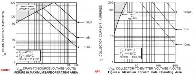
On the other hand looking at your IGBT from figure 9 you can see it can safely carry 100 Ampere at 100 deg C. From fig 3 you can derive that 100 Ampere will give around 2 V + drop across the device. Even if there is no exact data formula for calculating the dissipation at elevated temperatures, i think it's safe to say that your IGBT can also dissipate 100 * 2 = 200 W at 100 deg C. Which is pretty good for a BJT.
So
IGBT 200 W
MOSFET 425 W
(both at 65 deg C)
Looking at the datasheets of the MOSFET it can dissipate 625W at 25 deg C with 5W per deg linear derating. So at 65 deg this is 40 deg * 5 W deraing = 200 W derating. Right? And 625 - 200 is 425 W not 295 W.
On the other hand looking at your IGBT from figure 9 you can see it can safely carry 100 Ampere at 100 deg C. From fig 3 you can derive that 100 Ampere will give around 2 V + drop across the device. Even if there is no exact data formula for calculating the dissipation at elevated temperatures, i think it's safe to say that your IGBT can also dissipate 100 * 2 = 200 W at 100 deg C. Which is pretty good for a BJT.
So
IGBT 200 W
MOSFET 425 W
(both at 65 deg C)
Hi
Dear Lars,
I agree with you there was an error in my calculation.
Thanks for correcting me.
By the way kindly look at the SOA curve of mosfet and igbt and you will see a vast difference in current-voltage curves for both devices.
SOA curve --> mosfet-->VDS 80V-->ID 12A-->pulse 10mS
SOA curve --> igbt -->VCE 80V-->IC 36A-->pulse 10mS
There' s a huge difference in current capacity at 10mS pulse.
In my opinion IGBT still has the Edge over the Mosfet.
regards
Kanwar
Lars Clausen said:Thanks Kanwar, very interesting ;-)
Looking at the datasheets of the MOSFET it can dissipate 625W at 25 deg C with 5W per deg linear derating. So at 65 deg this is 40 deg * 5 W deraing = 200 W derating. Right? And 625 - 200 is 425 W not 295 W.
On the other hand looking at your IGBT from figure 9 you can see it can safely carry 100 Ampere at 100 deg C. From fig 3 you can derive that 100 Ampere will give around 2 V + drop across the device. Even if there is no exact data formula for calculating the dissipation at elevated temperatures, i think it's safe to say that your IGBT can also dissipate 100 * 2 = 200 W at 100 deg C. Which is pretty good for a BJT.
So
IGBT 200 W
MOSFET 425 W
(both at 65 deg C)
Dear Lars,
I agree with you there was an error in my calculation.
Thanks for correcting me.
By the way kindly look at the SOA curve of mosfet and igbt and you will see a vast difference in current-voltage curves for both devices.
SOA curve --> mosfet-->VDS 80V-->ID 12A-->pulse 10mS
SOA curve --> igbt -->VCE 80V-->IC 36A-->pulse 10mS
There' s a huge difference in current capacity at 10mS pulse.
In my opinion IGBT still has the Edge over the Mosfet.
regards
Kanwar
Attachments
Lars,
Aren't you being a little unfair to Kanwar's IGBTs suggesting a 200W rating due to 2vx100A on the saturation limit. You could equally well have used 4vx200A = 800W on the same curve. This is not definitive for the device dissipation.
Better to consider what it can do practically in an amplifier i.e. at the supply rail voltage of 80V Kanwar is using. Since they are essentially a BJT for power they should presumably be derated from the 390W case dissipation at 25C to 278W at 75C. This gives current of 3.5A at zero crossing for reactive (real) load driving ability. As with most rugged BJTs this can be relaxed due to pulse duration and duty cycle. In Kanwars application we can assume seconds+ and 50%, which could reasonably reliably double the current output ability given the ruggedness.
So I would put it at around 550W giving 7A at 80V rails. But where is that BJT second breakdown?
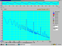
Can you imagine the hash on the supplies at such current /power levels. Attached is a pic of the supply of my 250W /8ohm amps supply rail on the circuit board when output is 5W rms into 8 ohms. See the induced harmonics due to the Class AB half currents. This is what lurks on every AB supply waiting for a poor PSRR stage referencing to the supplies.
Aren't you being a little unfair to Kanwar's IGBTs suggesting a 200W rating due to 2vx100A on the saturation limit. You could equally well have used 4vx200A = 800W on the same curve. This is not definitive for the device dissipation.
Better to consider what it can do practically in an amplifier i.e. at the supply rail voltage of 80V Kanwar is using. Since they are essentially a BJT for power they should presumably be derated from the 390W case dissipation at 25C to 278W at 75C. This gives current of 3.5A at zero crossing for reactive (real) load driving ability. As with most rugged BJTs this can be relaxed due to pulse duration and duty cycle. In Kanwars application we can assume seconds+ and 50%, which could reasonably reliably double the current output ability given the ruggedness.
So I would put it at around 550W giving 7A at 80V rails. But where is that BJT second breakdown?
Can you imagine the hash on the supplies at such current /power levels. Attached is a pic of the supply of my 250W /8ohm amps supply rail on the circuit board when output is 5W rms into 8 ohms. See the induced harmonics due to the Class AB half currents. This is what lurks on every AB supply waiting for a poor PSRR stage referencing to the supplies.
Attachments
- Status
- This old topic is closed. If you want to reopen this topic, contact a moderator using the "Report Post" button.
- Home
- Amplifiers
- Solid State
- What every Class AB builder needs to be constantly aware of