Greg wrote:
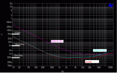
I made quick measurement of 2200uF and 22000uF Panasonic caps. They both are rated for 35V and belong to the same production series. The parasitic resistance of ten 2200uF caps in parallel can be 2mOhm; this is 5 times lower than the parasitic resistance of 22000uF (10mOhm). But for the money spend on 22000uF one can buy only three or four 2200uF caps. May be the price ratio can be different from another manufacturer.
It is common practice to put small cap (220-2200uF) near the output devices on pcb. It is generally accepted that all even hf harmonic current shortened through these small caps. Assume that the main caps connected by two one-foot 16 AWG wires (10mOhm), and the solder joints another 10mOhm. From this impedance measurement one can see that _only half_ is shortened through smaller pcb caps, and for signals _higher than 10 kHz_.
Now with each output half having to deliver half the waveform, just look at the spray of harmonics that are generated in and around the outputs and power supply lines.
Can you imagine the hash on the supplies at such current /power levels. Attached is a pic of the supply of my 250W /8ohm amps supply rail on the circuit board when output is 5W rms into 8 ohms. See the induced harmonics due to the Class AB half currents. This is what lurks on every AB supply waiting for a poor PSRR stage referencing to the supplies.
I made quick measurement of 2200uF and 22000uF Panasonic caps. They both are rated for 35V and belong to the same production series. The parasitic resistance of ten 2200uF caps in parallel can be 2mOhm; this is 5 times lower than the parasitic resistance of 22000uF (10mOhm). But for the money spend on 22000uF one can buy only three or four 2200uF caps. May be the price ratio can be different from another manufacturer.
It is common practice to put small cap (220-2200uF) near the output devices on pcb. It is generally accepted that all even hf harmonic current shortened through these small caps. Assume that the main caps connected by two one-foot 16 AWG wires (10mOhm), and the solder joints another 10mOhm. From this impedance measurement one can see that _only half_ is shortened through smaller pcb caps, and for signals _higher than 10 kHz_.
Attachments
dimitri said:I made quick measurement of 2200uF and 22000uF Panasonic caps. They both are rated for 35V and belong to the same production series. The parasitic resistance of ten 2200uF caps in parallel can be 2mOhm; this is 5 times lower than the parasitic resistance of 22000uF (10mOhm). But for the money spend on 22000uF one can buy only three or four 2200uF caps. May be the price ratio can be different from another manufacturer.
I've been parallelling small value caps since the high 80s in my diy stuff.
For a diy-er this can actually be an advantage, often a large number of smaller capacitors can be bought for far less than a big one.
Another advantage is the often smaller volume required, which in return makes the amplifier chassis a size smaller ; less money, less raw material.
Not so long ago i bought a large box of 4700uF surplus Roe capacitors for 15% of the msrp, they will serve my needs for some time.
Originally posted by amplifierguru You sure you would not be partaking of some illicit herbs? This is worth doing, right? SIMPLE. I don't think so.
Welcome to the party, Guru,
I dont think it so maybe you misunderstood my acknowlodgement , since you again definately lack the perspectiveness of the context in relation to professsional amps.
i know very well that you were a pro designer, thats why i just say to you have cup of nice cofee and relax .
Hi Dimitri,
Yes paralleling smaller PS caps is indeed an exercise of diminishing returns but I do it, Jacco does it not only for the economies of scale (buying 10xthe quantities) or the feelgood factor but a further good reason - it splits the internal resistance heating over several components and has to bode well for component longevity especially at high current/arduous operation. I even went to the extent of stripping my 16 PS caps in the Eidetic amp of their plastic sheath so they could better exude their self heat for longer life ( in a well ventilated chassis). But, as you say, wiring and solder joints get in the way of low Z in the supply and this can add up to superimpose output stage harmonics on the supplies, to a significant extent - to where it can dominate the THD of the amplifier.
But there's another aspect - apart from the supply impedance issue. The currents flow in the output halves and these radiate into surrounding board areas so are picked up there through poor board geography. All too often boards are laid out on FIT or FLOW rather than any higher understanding of the circulating currents/circuit impedances and many a good concept is nobbled at the implementation.
As Douglas Self poo-pood my PSRR article then, in his series, regulated the PS for a reduction in THD from 0.04% down to 0.006% - probably the single most significant mod in his series!!!
Kanwar,
Indeed my judgement may well be going, but it's still to pass yours in it's decline. Nchannel madness.
amplifierguru said:Kanwar,
Indeed my judgement may well be going, but it's still to pass yours in it's decline. Nchannel madness.
hello Guru,
Maybe a powerware solution is greatly examplated through the N-channel Mosfets only, in which your do not entertain a subsequent territory. Well is it quite that simple for you to say something without .........
Have a nice day , and suggest good circuits to everybody because you are after all a guru of amplifiers of the world.
best regards,
kanwar
amplifierguru said:it splits the internal resistance heating over several components and has to bode well for component longevity especially at high current/arduous operation. I even went to the extent of stripping my 16 PS caps in the Eidetic amp of their plastic sheath so they could better exude their self heat for longer life
For the risk of becoming the fall guy i did not add to my posting that, imo, the larger external area of an equivalent number of small capacitors, relative to one big specimen, should improove cooling and therefore add to longevity.
If plastic sheating can have has such a significant effect, why are capacitors sheated, it seems like the worst in both worlds ?
On another thread i just posted on terminal blocks and crimp sleeving. A company as wbt prooved a long time ago that screwed and sleeved connections have far better conductivity than soldered ones for high currents.
I'd like to see a PS as a big powerplant in need of large powerlines, but those need ample distance and shielding as not to interact with the main theme.
The funny thing i noticed on a number of ocassions on this forum is people advocating to squeeze components and traces as close as physically possible.
It need not be either/or, true ?
it splits the internal resistance heating over several components and has to bode well for component longevity especially at high current/arduous operation. I even went to the extent of stripping my 16 PS caps in the Eidetic amp of their plastic sheath so they could better exude their self heat for longer life
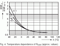
The higher the operating temperature, the shorter caps life, yes, but the ESR declines two times with increasing temperature from 20°C to 40°C, so better keep ‘em warm.
further good reason - it splits the internal resistance
When caps are connected in parallel thermal imbalances between them is important. Thermal runaway may occur if they are unbalanced which could lead to cap failure.
Attachments
Thanks for posting that dimitri. But you might note that the ambient temps seen by many electros are already in the significant ageing effect range, especially in 'cooking' amp chassis running high bias AB or Class A!
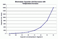
Perhaps you have handy a similar temp graph for the ageing of electros and we can might just find the optimum in the range 25-50C so you would only want to warm them in cool climes and then it's diminishing returns for the ESR much beyond 25C. Better to desensitise the amp to such vagaries or you will be hearing your Cs warming up.
I'm sure Kanwar would be looking for an icepack for his with 50C ambients and a 75C chassis. That's only 4000 hours lifetime for an 85C cap. And that's before it falls over?
surely I have, inside my poor headPerhaps you have handy a similar temp graph for the ageing of electros
Every 10° C increase in internal temperature halves the cap lifetime.
Greg,That's only 4000 hours lifetime for an 85C cap
If you will take so much care about the amplifier lifetime, what will you design/sell afterwards?
 I remember during tube era I was taught to keep elcos as far from output tubes and trafo as possible...
Attachments
amplifierguru said:I'm sure Kanwar would be looking for an icepack for his with 50C ambients and a 75C chassis. That's only 4000 hours lifetime for an 85C cap. And that's before it falls over?
Hey Greg, I dont need an icepack, since our chasis temp never exceeds above 65.C because heatsinks are totally isolated from the chasis becuse they carry voltages as we mount the devices directly to them without insulators. regarding our caps they also stay more cool than you, as they have arrange ment of efficient cooling through fans as well. So you dont have to worry for that and take care of yourselve please.
Workhorse said:Our chasis temp never exceeds above 65.C because heatsinks are totally isolated from the chasis becuse they carry voltages as we mount the devices directly to them without insulators.
I recollect the temperature range you posted, Kanwar.
What lifespan of the electrolytics must we think of in your area, with those numbers ?
Sorry Kanwar, my recollection was that you designed your amps for a 75C operation.
Dimitri,
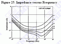
On the subject of multiple paralleled smaller capacitors compared with one large one, do you have the graphs of impedance vs frequency to locate the max frequency tey are still acting as a capacitor - before the inductance kicks in! That would be of value here.
Dimitri,
On the subject of multiple paralleled smaller capacitors compared with one large one, do you have the graphs of impedance vs frequency to locate the max frequency tey are still acting as a capacitor - before the inductance kicks in! That would be of value here.
There is a general rule of thumb that chemical reactions double their rate for every 10°C rise in temp - seems thet perhaps this has something to do with the lifetime of electrolytic caps which are perhaps the least reliable of electronic components - given that the design does not overly strain something, that is is a 1W resistor operating at 0.5 watts works for a looooooong time, a elec cap even if working within its voltage, ripple current and temp rating still goes bad.
Yes absolutely - and this is borne out by the electro's characteristic doubling of lifetime with every 10C below their lifetime rating. Trouble is they go 'soft' well before their indicated lifetime. That's why in an earlier post I indicated that the rating was when they 'fall over'.
So a supply electro rated at 2000hrs @ 85C will have an extended lifetime at 65C of 8,000hrs before it 'falls over' but may 'go soft' after 400hrs due to conditions - temperature cycling, peak currents, charge/discharge rates/memory effect, etc...
Smaller, say 10x 2,200uF ( Dimitri's example) will have distributed heating rather than centralised and possibly less shock (of operation) in use.
Either way, cooking chassis are BAAaaad design.
Hi,
that impedance diagram is a surprise.
Intuitively I would expect the impedance reduction to be about 5 times lower or a little higher say 4 times for 5 in parallel.
The gain in impedance lowering is better than divide by 5 over a large part of the frequency range. It even shows better than 10 times lower and over a small range must be about 100 times lower.
The impedance minima shows a trend towards higher frequency as more are added.
Can anyone explain what is happening here?
- Status
- This old topic is closed. If you want to reopen this topic, contact a moderator using the "Report Post" button.
- Home
- Amplifiers
- Solid State
- What every Class AB builder needs to be constantly aware of


