Sounds like you want mirror image subs, so design for four drivers with a side exit like a DSL TH-SPUD, build two and flop one over to get their exits up against the wall/floor junction (1 pi loading) or if the bulk/weight isn't an issue, just make one big one with a common divider.
GM
GM
Exactly! I would prefer the two enclosure option with 4x5" drivers in each TH design,to have the possibility and place the two cabs side by side either aligned with their mouth exits on the left and on the right along the floor and wall or rotated for 90 degrees to have both mouths centered on the front of both cabs.
(2nd option: TH-221/TH-412 style)
Another thing to worry about: if both mouth couplers are located in the middle radiating to the front and separated from each other by the enclosure walls of each cab, wouldn't it be more efficient to make use of only one common mouth coupler for both THs?
(referring to danley's patent about TH design)
I know that feeling: "I have, therefore I [feel like somehow I] must use"I understand what you mean and I know that these drivers aren't well suited for a sub application, regardless I would like to try to get the maximum out of them and to find the most efficient enclosure for such a "unusual subwoofer driver".
But they really aren't well suited, Fs is double the Q. So maybe a horn, or yes a VERY heavily EQ'd sealed box. But in reality you are probably much better off getting a better driver(s), the 5s may just not be that linear if they are cheap.
I am 127% sure those drivers have very different parameters from what you have. And yeah, they do EQ the heck out of them, that's why Bose 901s have an outboard EQ module. In the Acoustimass systems it is built in..How knows what those bose type acoustimass drivers are able to do, what excursion are they capable? Isn't it, that bose squeezes an amount of low end and spl out of some low pricey drivers as well? Or am I completely wrong with this presumption?
gzg
Flexible design
Hi Ibex,
From a design viewpoint it makes sense to do a layout for a dual driver tapped horn for your application. Then you can stack them any way you like to.
Tapped horns seem to be very forgiving as to the direction/location of the mouth, as long as the general dimensions established in the Hornresp simulation are not violated.
Regards,
Attachments
Tapped horns seem to be very forgiving as to the direction/location of the mouth...........
Tell that to the guys with the DTS-10s over on AVS.......
") A lot of backs got tweaked moving them around trying to find a good in-room position.
A lot of backs got tweaked moving them around trying to find a good in-room position. GM
Hi GM,
I agree, the in room location is important. As is the number of enclosures. And not enough work seems to be going on as far as room tuning/treatment/trapping is concerned.
I was referring to the direction of the mouth in relation to the box, axially in line w/ the horn, or at a right angle to the horn axis. There seem to have been quite a few experiments even on the AVS DTS-10 thread.
You are definitely right that experimenting might come into play, and then there is the problem with that pesky furniture location acceptance factor.
Regards,
I agree, the in room location is important. As is the number of enclosures. And not enough work seems to be going on as far as room tuning/treatment/trapping is concerned.
I was referring to the direction of the mouth in relation to the box, axially in line w/ the horn, or at a right angle to the horn axis. There seem to have been quite a few experiments even on the AVS DTS-10 thread.
You are definitely right that experimenting might come into play, and then there is the problem with that pesky furniture location acceptance factor
.Regards,
Advanced Tapped Horn versus simple Ported/Reflex
Hi guys,
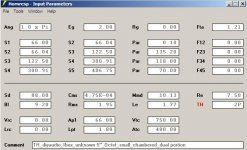
I'm pretty upset, cause HR was predicting better results for and simple reflex design in comparison to an advanced tapped horn using the same driver. I always thought, that a TH offers less excursion for the same effiency and low end or more spl and more low end for the same cone movement?
Please tell me, that I made something wrong with the simulations, unless I'll get completeley nuts...
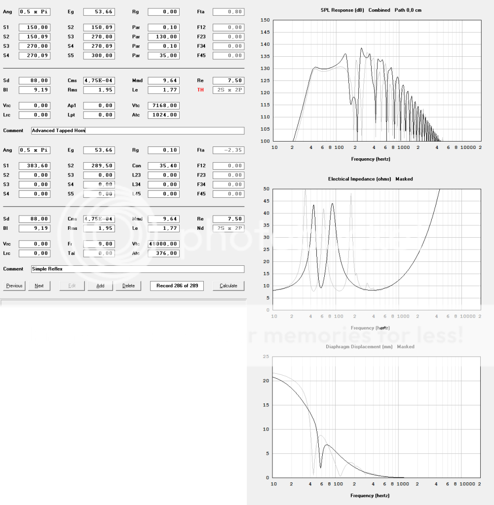
Watch out the HR data/plots:
black = ported/reflex
grey = tapped horn
Hi guys,
I'm pretty upset, cause HR was predicting better results for and simple reflex design in comparison to an advanced tapped horn using the same driver. I always thought, that a TH offers less excursion for the same effiency and low end or more spl and more low end for the same cone movement?
Please tell me, that I made something wrong with the simulations, unless I'll get completeley nuts...
Watch out the HR data/plots:
black = ported/reflex
grey = tapped horn
Please tell me, that I made something wrong with the simulations...
Ditto,
I smell burning coils in a rookie wishful thinking tombola design showing a TH that only would survive frequencies above 100 Hz. Your 'Ported' (Nd-pipe in reality) is clipping severely for frequencies below ~180Hz.
Compare you HR designs with my(not commented) earlier posted simulation.
What's wrong with the SPL I achieved in my simulation?
It's IMO clear
you have little knowledge how to use HR.b
Without having time to really look at this: the BR is not a BR, it is a 163cm long tube with a reduced opening on one end, and the four drivers on the other end.
Your 'Ported' (Nd-pipe in reality) is clipping severely for frequencies below ~180Hz.
I have to agree with you, it's not the most accurate simulation. To make it more precise I would have to write a script for Akabak.
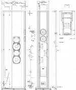
I tried to model the original reflex cab, which I got the drivers from.
In fact it concerns an enclosure which is 127.5cm tall with an 376cm² footprint, the drivers aren't mounted at the beginning of the line, but in the middle of the whole cab. At the bottom resides the port which offers an average length of 35.4cm and exhibits an cross sectional area equal to the footprint of the cab.
The biggest challenge to make an 100% congruent Akabak model of the cab would be to implement the fluctuating port legth into the script.
Have you got a clue how to do this?
Attached there you have the enclosure design in detail:
Attachments
Compare you HR designs with my(not commented) earlier posted simulation.
What's wrong with the SPL I achieved in my simulation?
Of course, your T-TQWP suggestion looks promising!
Would it be possible to mount the rear of the drivers into a as small as possible rear/comression chamber and attach this chamber at the beginning of the pipe/horn throat as well?
Why did you choose a pipe instead of a horn?
How do you get the 8 small circles/drivers instead of one big one in the schematic diagram?
Why would mine only survive frequencies above 100Hz?
Do you think that the fb of the TH design is way to low for these cheapo drivers and the can't handle it? Or is something else wrong with my tombola TH which offers a almost similar response to your T-TQWP enclosure suggestion?
Hi,
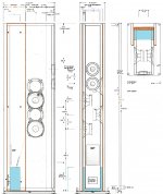
I tried to make the drawing more legible and marked the beginning (blue area) and the end (orange area) of the port, I reentered the necessary measurments including the internal width/depth/height as well... (depth = 32.7)
I'm pretty sure that there are no internal dividers, I took a look inside the cab.
Attachments
Hi Ibex,
Yes, the coloring helps.
It looks like the areas/volumes in blue and the immediately adjacent brown areas/volumes can be treated as part of the chamber volume. From there the porting is through slots leading out between the chamber walls, the base board and a couple of side mounted loading boards. The distance from the chamber volume to the outside at the bottom (sides, back and front) is so short (essentially the thickness of the loading board at the sides), that I doubt that there can be significant loading of the slot upwards. So you have a relatively short distributed slot port tuning a very long vertical column, almost like a MLTL, with the drivers mounted in the middle of the sides.
I wonder whether this was done for the sound or for the looks. It may help to run some impedance and frequency response curves.
Anyway, have fun modeling this.
Regards,
Indeed, some kind of mass loaded transmission line...
The gap between the main enclosure walls and the side mounted boards measures 6mm.
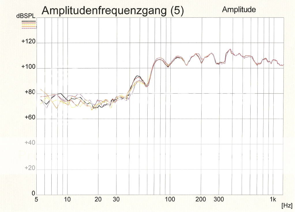
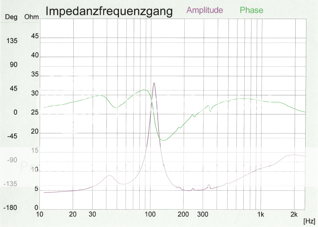
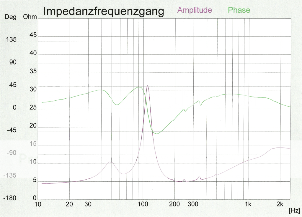
Fortunately I have made some impedance and response plots with and without the sideboards attached some time ago. Due to it is a inroom response it has only a limited significance, but it is possible to distinguish a slightly increased low end around 50hz.
Here we go:
black/red: with sideboards
yellow/orange/magenta: without sideboards
with sideboards
without sideboards
The gap between the main enclosure walls and the side mounted boards measures 6mm.
Fortunately I have made some impedance and response plots with and without the sideboards attached some time ago. Due to it is a inroom response it has only a limited significance, but it is possible to distinguish a slightly increased low end around 50hz.
Here we go:
black/red: with sideboards
yellow/orange/magenta: without sideboards
with sideboards
without sideboards
...You need a subwoofer.
Gradually I become aware of the fact, that it is almost impossible to design a thx frequency capable enclosure around these cheapo 5" drivers, even if I stick 8 of them into the sub to archieve serious air movement which is necessary for such low frequency sound reproduction systems and even if I try to get the most out of them with a proper designed advanced multiple tuned and horn loaded enclosure which pulls out all the stops.
What a pity!
Unfortunately it seems that I was to optimistic, due to the fact that bose acoustimass subs are utilizing 5inch woofers as well to create enough amount of sub bass information needed in home cinema systems, but obviously the used drivers are probably more suitable for such an application than mine...?
.......due to the fact that bose acoustimass subs are utilizing 5inch woofers as well to create enough amount of sub bass information needed in home cinema systems...........
Since when?!
GM
So, bose do not archieve more low end nor more max SPL with their subs than a TH driven by the above mentioned 5inch "woofers"?
Well, I do not believe that the bose subs are great for home cinema purpose nor quality hifi-sound...
...but wouldn't building a sub with my cheapo drivers then be worth a try or just waste of time?
bjorno smells burning coils
Well, I do not believe that the bose subs are great for home cinema purpose nor quality hifi-sound...
...but wouldn't building a sub with my cheapo drivers then be worth a try or just waste of time?
bjorno smells burning coils
- Status
- This old topic is closed. If you want to reopen this topic, contact a moderator using the "Report Post" button.
- Home
- Loudspeakers
- Subwoofers
- What enclosure type for this cheap trick driver?