Hi yu3ma,
You are exactly right! Both HP/Agilent/Keysight and Tektronix have a lot of fantastic information on using your oscilloscope, and also on which lead to use and when. Reading up on these things is the best education you can give yourself (and for free!!!).
yu3ma, you missed the solder-on jacks for the probes where the ground connection is shorter still. This still allows you to browse your test points, except with proper grounding.
I think what you are saying (and you are so right about this) is that how you use an instrument determines what you will get out of it. Even with modest equipment, knowledge will give you the right answers - assuming the equipment is up to the task.
-Chris
Beside having oscilloscope it is more important how you will make the measurements as there are many problematic point especially if you looking for some low values of signal or working with high speed signal.
Here is one practical example how you can be fooled to have "something" in your signal but after considering the effect of parasitic inductivity of just 10-15cm GND cable of oscilloscope probe you can have much clear picture.
First and second picture show standard way to measure something and results of that measuring, but that is not correct for some application. Other two picture show correct method for most application.
PS: this is example of measuring high sped signal which have about 1500V/us slew-rate. Such high slew rate can be found in almost every SMPS and it is very important to use proper method. Similar is with measuring (AC coupled) noise or ripple of some linear regulator.
Yes! The first picture shows one such accessory that should be supplied with a new probe. Another is the one that you can stick the tip of the probe in and then directly connect to a BNC (used in the video I linked to in my previous post). BTW, that video may be a bit long if you don't have time, but well worth watching because it shows how much can go wrong and how easily that can happen without becoming too technical.
I'm going to work now, so I'll post the capture later.
Last edited:
@anatech
Yes, you are right, solder-on jacks for the probes are the best option. I did'n have any at a moment to take a picture. Who knows about those measuring problems they probably knows about that jacks")
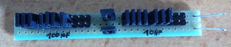
Back on topic, another very useful and simple tool which can help you to trim the FB compensation in order to stabilize regulator or improve transient response on practical implementation, I call this tool "Poor man's decade capacitor box" (10x10nF + 10x100nF SMD capacitors + jumpers)
When testing regulator for transient response (mentioned in post #8 and #9), whit such tools simple replace existing capacitor in FB path of regulator and observe the response at output.
Try different combination of jumpers (different capacitor values) until you get the lowest over and under shots and get rid of "ringing". When you find the best combination, simple measure the capacitance of those tool and replace with equivalent value capacitor in your regulator.
It is not the perfect method to do things right but it very easy method and can greatly help to stabilize/improve FB of regulator (or amplifier).
Also with some trimer/potentiometer resistor replace R in FB path and again try to find the best results.
At the end you will have quite close to optimal values of R and C for FB compensation.
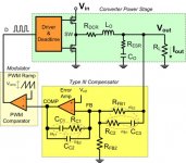
Second picture is just for reference on what R/C values I mean. It is usually the same in all implementation, just types of compensation differ (Type I, II, III …)
Yes, you are right, solder-on jacks for the probes are the best option. I did'n have any at a moment to take a picture. Who knows about those measuring problems they probably knows about that jacks
Back on topic, another very useful and simple tool which can help you to trim the FB compensation in order to stabilize regulator or improve transient response on practical implementation, I call this tool "Poor man's decade capacitor box" (10x10nF + 10x100nF SMD capacitors + jumpers)
When testing regulator for transient response (mentioned in post #8 and #9), whit such tools simple replace existing capacitor in FB path of regulator and observe the response at output.
Try different combination of jumpers (different capacitor values) until you get the lowest over and under shots and get rid of "ringing". When you find the best combination, simple measure the capacitance of those tool and replace with equivalent value capacitor in your regulator.
It is not the perfect method to do things right but it very easy method and can greatly help to stabilize/improve FB of regulator (or amplifier).
Also with some trimer/potentiometer resistor replace R in FB path and again try to find the best results.
At the end you will have quite close to optimal values of R and C for FB compensation.
Second picture is just for reference on what R/C values I mean. It is usually the same in all implementation, just types of compensation differ (Type I, II, III …)
Attachments
Last edited:
Here's the image I promised a couple of days ago:
This is what happens to an LM337 if you get caps on the output wrong. It's a behaviour that LDOs (low dropout regulators) are much more prone to than normal dropout regulators.
As you can see, the oscillation frequency is well within the audio band and with 830 mVpp pretty strong. The oscillations were present at room temperature but disappeared after warming up, pointing to a marginally stable design. This only became obvious after a couple of thousand units when a somewhat more sensitive batch of LM337 came along.
The solution was to put a very small resistance (< 0.25 Ohms) in series with the output pin.
An externally hosted image should be here but it was not working when we last tested it.
This is what happens to an LM337 if you get caps on the output wrong. It's a behaviour that LDOs (low dropout regulators) are much more prone to than normal dropout regulators.
As you can see, the oscillation frequency is well within the audio band and with 830 mVpp pretty strong. The oscillations were present at room temperature but disappeared after warming up, pointing to a marginally stable design. This only became obvious after a couple of thousand units when a somewhat more sensitive batch of LM337 came along.
The solution was to put a very small resistance (< 0.25 Ohms) in series with the output pin.
Last edited:
Hi jitter,
That's pretty graphic. I haven't had the pleasure of seeing this exact behavior. You are absolutely right in that it is a pretty strong oscillation.
It's interesting to see the leading edge "pip" on the waveform. I normally see something like this at 120 Hz due to filter capacitor inductance and ESR as the caps age. On this you can clearly see an almost perfect constant current discharge, like a relaxation oscillator.
Nice 'scope BTW.
Hi Chris,
About 75% of that batch of LM337 (from OnSemi) exhibited this behaviour at room temperature. The oscillations would be strong at first and during warming up you would see the oscillation go up in frequency (but no big change in amplitude) followed by the scope getting difficulty triggering (displaying two, slightly offset saw tooths). That was the sign that the oscillation would soon and suddenly disappear.
At first we suspected the LM337, but after some experimentation with freeze spray found that older batches could be made to oscillate too, pointing towards the design of the circuit.
Research pointed towards a marginally stable setup. In this case the ESR of the caps on the output was too low and it was suspected that the ESR of the supplied tantalums (always the same brand and type) had gradually become lower during the years this unit was in production. Hence the rather late discovery of the design flaw.
I also came across oscillations with another linear regulator that oscillated as a result of too high ESR. I believe this did not look like a sawtooth.
One thing worth commenting on is the pip in the leading edge you mentioned. We're talking about a measuring instrument of which I obviuoulsy can't reveal any details.
After the functional tests are completed, a set of measurements is made using well known calibrated resistive and reactive loads. The resulting plots show if the instrument performs to specification.
In a whole set of measurements, this huge oscillation only showed up in two. And in one of the two, it was only the pip part that filtered through. My guess is that the PSRR of the opamps did a good job, but I'm not sure.
But all this goes to show that even experienced designers get the relatively simple parts of a circuit wrong sometimes (perhaps concentrating too much on the complicated parts)...
If that particular batch of LM337 had not found its way onto the units, we would probably still be unaware of the design flaw. In defense of the designer I will say that a somewhat older golden board could not be made to oscillate with all the effort in the world. So, it's likely that during the prototype phase of the design checks for instability would not have found any problems.
Sorry if I'm getting a bit off topic..
Last edited:
Hi jitter,
Well, we are on topic. Just imagine other people running into this. I am grateful you posted this picture.
No names needed, or equipment ID. Mind you, I am a test equipment centric kind of guy and collect / restore test equipment for myself. There is a curiosity now.
I think most designers fail to apply proper design to power supplies these days. Protection diodes are almost always missing, and capacitor types seem to be picked at random. I only trust wet slug tantalum capacitors, or the usual others. Lately the capacitors for switch mode power supplies find their way into my stuff.
-Chris
Well, we are on topic. Just imagine other people running into this. I am grateful you posted this picture.
No names needed, or equipment ID. Mind you, I am a test equipment centric kind of guy and collect / restore test equipment for myself. There is a curiosity now.
I think most designers fail to apply proper design to power supplies these days. Protection diodes are almost always missing, and capacitor types seem to be picked at random. I only trust wet slug tantalum capacitors, or the usual others. Lately the capacitors for switch mode power supplies find their way into my stuff.
If you were to figure out what the equivalent frequency was for that "pip", you would likely see the PSRR wasn't that great "up there". That must have taken some time to prove your findings were valid. Those are the tough problems to figure out. Good going!it was only the pip part that filtered through.
-Chris
There was an article in ED where Pease mentioned to use designated GND connection of CRO and not to use the one on the probe for low level signals.
This looks like a good book to refer
Troubleshooting Analog Circuits (EDN Series for Design Engineers): Amazon.co.uk: Robert Pease: 9780750694995: Books
Gajanan Phadte
This looks like a good book to refer
Troubleshooting Analog Circuits (EDN Series for Design Engineers): Amazon.co.uk: Robert Pease: 9780750694995: Books
Gajanan Phadte
Last edited:
Hi Gajanan,
Yep, a good read. Common sense is invoked at every opportunity.
There are times when you do use the probe ground though, and you can't lay down a hard and fast rule to cover all circumstances. I use the 'scope ground connection for low frequency, higher level signals when I am troubleshooting. For anything else you should use the closest common point to the signal you are measuring.
-Chris
Thanks for all the good posts guys. Jitter, thanks for posting the picture, I sure didn't expect to see something that strong and sawtooth. I've heard LDO's are a pain and I never would have guessed that too low of an ESR would've caused a problem.
I watch EEV's vids all the time and recently saw this one on measuring PSU noise: https://www.youtube.com/watch?v=Edel3eduRj4
But he didn't show an example what an oscillation looks like so I don't really know what a linear regulator will do in that scenario. My scope is so old that I halfway don't trust it when it gets down to the 5m and 2m V/div anyway. I ordered a Rigol DS1054Z a month ago and they are telling me that it won't ship until next month. Apparently it's a problem with Rigol not being able to keep up with the demand and there was some kind of shipping port strike on the west cost.
When I get it, I think I'll breadboard up a PSU and TRY to make it oscillate by putting no caps on it so I get an idea of what to look for. Thanks again for all of the advice!
Thanks for the link, I'll certainly watch it.
I like his videos as well, and I already learnt a thing or two. I had to get used to his squeaky voice at first but now there are "no worries, mate".
I'm interested in that DS1054Z too, and here too people have to wait... Perhaps it's so popular because of it's fantastic price/quality ratio and the fact that the hardware is capable of 100 MHz (and apparantly there's a way to unlock the 100 MHz capability by hacking the firmware).
A low ESR cap like a tantalum or a somewhat bigger (1 uF or so) ceramic might help get it oscillating. I must say that temperature also played a role. The colder, the easier the oscillations occurred. So a bit of freeze spray (or spray duster, held upside down) might also do the trick...
I like his videos as well, and I already learnt a thing or two. I had to get used to his squeaky voice at first but now there are "no worries, mate"
.I'm interested in that DS1054Z too, and here too people have to wait... Perhaps it's so popular because of it's fantastic price/quality ratio and the fact that the hardware is capable of 100 MHz (and apparantly there's a way to unlock the 100 MHz capability by hacking the firmware).
A low ESR cap like a tantalum or a somewhat bigger (1 uF or so) ceramic might help get it oscillating. I must say that temperature also played a role. The colder, the easier the oscillations occurred. So a bit of freeze spray (or spray duster, held upside down) might also do the trick...
Last edited:
Hi shredhead,
Looks like you are on the road to happiness.
We'll all get there eventually. Thanks for being a cool Mod, Chris.
I'll be sure to show you guys the screen caps on the new scope. See ya in a month hopefully. -Paul
Last edited:
a little experiment
Perhaps relevant to this thread is the behaviour of my old Voltcraft PS-2403D under load.
I never really liked it, but at the time I bought it (1998) it was a quite capable dual PSU for the money. Two shortcomings: no master/slave tracking and it never lost the pungeant smell of the wire/transformer lacquer.
For a couple of hours now I'm torturing it a little, running it close to max load with the heatsinks covered (yes, the thermal protection works).
I also put a scope on the (paralleled) outputs to see what the ripple was like under load, that was a little more than I expected and there's some ringing too (it's running constant current mode).
That kind of ringing may also occur on the output of a regulator as a reaction to load transients if it's badly designed.
Below is the output of this PSU with both channels paralleled and driving an H4 carbulb with the two filaments in series. With voltage and current fully open, it reaches 33 V and 2x 3 A giving a total power output of nearly 200 W, near enough its max. of 240 W. While supplying 200 W it draws 340 W, now I'm going to do the same thing to an industrial SMPS, I'm expecting a far better efficiency, and probably also less ripple.
The vertical scale is set to 50 mV/div (1x probe).

Close up of the ringing:

Perhaps relevant to this thread is the behaviour of my old Voltcraft PS-2403D under load.
I never really liked it, but at the time I bought it (1998) it was a quite capable dual PSU for the money. Two shortcomings: no master/slave tracking and it never lost the pungeant smell of the wire/transformer lacquer.
For a couple of hours now I'm torturing it a little, running it close to max load with the heatsinks covered (yes, the thermal protection works).
I also put a scope on the (paralleled) outputs to see what the ripple was like under load, that was a little more than I expected and there's some ringing too (it's running constant current mode).
That kind of ringing may also occur on the output of a regulator as a reaction to load transients if it's badly designed.
Below is the output of this PSU with both channels paralleled and driving an H4 carbulb with the two filaments in series. With voltage and current fully open, it reaches 33 V and 2x 3 A giving a total power output of nearly 200 W, near enough its max. of 240 W. While supplying 200 W it draws 340 W, now I'm going to do the same thing to an industrial SMPS, I'm expecting a far better efficiency, and probably also less ripple.
The vertical scale is set to 50 mV/div (1x probe).
Close up of the ringing:
Last edited:
And now a Power One FNP-1024G.
Loaded this one on the 24 V output (capable of 12.5 A) with two H4 bulbs, both filaments wired in series. Measured output current: 10 A, @ 24 V, so 240 W while drawing 260 W. A hole lot more efficient (as expected, of course) than the linear PSU (92% vs 59%).
Same vertical scale, horizontal 2 us/div.
This output also shows some ringing. Peaks are higher than you can see in the photo, but this scope is on the way out, intensity is set to max but the trace hardly registers. Not bad for a PSU rated at 300 W that you could hold in the palm of your hand.
An externally hosted image should be here but it was not working when we last tested it.
Hi jitter,
The Power One shot may just be the commutation cycle and inherent ringing. At this high current, the output choke doesn't completely filter out the ringing. I'll bet this is within specification.
That poor little Voltcraft isn't surprising us at all. It looks like an iffy error amp with poor HF response allowing the rectifier hash through. You should try and put the Y1 before the regulator circuit, but right on the input to that circuit. The Y2 shows what you have there. This should be illuminating.
What is the model number for that Philips 'scope? It looks a touch earlier than my PM3070. They normally have CRTs that go the distance. Have you tried to take the front bezel off and clean the tube and the filter? That might help it along a bit. Also, have you replaced the capacitors in the power supply. This is too nice a 'scope to fire into the bin. Those new 'scopes with all the features at a low price? Often they can only withstand 5 Vpeak on the inputs. 50 Vpeak using a 10:1 probe. I killed one thinking the 9 Meg in series wouldn't allow damage. Wrong! You may very well need this 'scope on the bench.
I had to rebuild the power supply in a pair of PM3070 'scopes. Made a world of difference. They were mostly axial lead types.
Philips generally does CRTs well, but circuit boards with sm components typically overheat. That is a section of PCB as well as individual components.
-Chris
Hi shredhead,
Thanks for being a cool ModMany thanks, but most are far more cool than I will ever be! I'm a grumpy old technician!
-Chris
Hi Chris,
Output voltage ripple and noise is specced at 120 mVpp max (20 MHz BW and Io = 12.5 A). But even at less than half load (one H4 bulb) it looks like this:
I did put the probe directly on the output of the PSU, not using the clip on earth lead, so I wonder what I'm doing wrong to get a higher Vpp reading than specified. The scope is set to 50 mV/div and 2 us/div, the probe is set to 1x and at that setting has a bandwidth of 17 MHz (150 MHz at 10x).
To confirm this result I dug out my old PC and Velleman K7103 32 MS/s DSO. This thing has a worhtless triggering circuit, and seems to miss the narrow peaks most of the time, but I got this:
I'm not sure if I understood this correctly, but here's what I tried.
With "Y1" and "Y2" I take it you mean channels A and B (or 1 and 2) of a scope.
Here's the Voltcraft again with both channels in CC mode. CH A shows the voltage on the collector of one of the output transistors (1 V/div), CH B the output ripple and noise (50 mV/div). Mains here is 50 Hz, so timebase is set to 2 mV/div.
This is the worst case situation, because if I lower the voltage just enough to have one of the PSU channels go into CV mode, that ripple and ringing on the output drop to just 1/10th of what you see here. But the ringing does remain present. If I change the timebase to 0.5 ms/div, I can see about a single division between the crest of the signal (ripple) on CH A and when the ringing starts on CH B.
The photos will have revealed the model. Datcodes I could see on some components place its production date somewhere around 1989/1990.
I'm familiar with the PM3070, we still have one at work, although it's hardly ever used anymore.
As you can see I cleaned the front and between the tube and filter. The pictures I took yesterday were under brighter conditions, so the trace looked even dimmer than in reality.
However, sometimes trace intensity seems to abruptly drop to about half of what's normal. It's intermittent and seems to be related to turning the timescale knob. At the moment it's fine, though.
Also both vertical scale knobs are very touchy. The signal really drops out or shifts up and down. After some use I would have thought that any oxidation would have been scraped off by now, but it doesn't seem to matter. CH B is less affected than A. I wonder if this is the result of oxidation or wear...
I took this scope home from work when it was discarded on the basis that the XY (X-deflect as it's called on this one) was supposedly defective (selected on this scope by the timescale knob, one click below the slowest scale).
Oh, I'm not going to discard it. I haven't changed any caps yet. I did measure the electolytics with an ESR meter, and they seemed to be just fine.
The scope I'm interested in (Rigol DS1054Z) has the following specs on the input:
"Max Input Voltage (1MΩ) Analog channel:
CAT I 300 Vrms, CAT II 100 Vrms, transient overvoltage 1000 Vpk
With RP2200 10:1 probe: CAT II 300 Vrms"
But didn't you say you killed one of these (or similar)?
All radial electrolytics and only through hole in the '3208.
Hi jitter,
The Power One shot may just be the commutation cycle and inherent ringing. At this high current, the output choke doesn't completely filter out the ringing. I'll bet this is within specification.
Output voltage ripple and noise is specced at 120 mVpp max (20 MHz BW and Io = 12.5 A). But even at less than half load (one H4 bulb) it looks like this:
An externally hosted image should be here but it was not working when we last tested it.
I did put the probe directly on the output of the PSU, not using the clip on earth lead, so I wonder what I'm doing wrong to get a higher Vpp reading than specified. The scope is set to 50 mV/div and 2 us/div, the probe is set to 1x and at that setting has a bandwidth of 17 MHz (150 MHz at 10x).
To confirm this result I dug out my old PC and Velleman K7103 32 MS/s DSO. This thing has a worhtless triggering circuit, and seems to miss the narrow peaks most of the time, but I got this:
An externally hosted image should be here but it was not working when we last tested it.
That poor little Voltcraft isn't surprising us at all. It looks like an iffy error amp with poor HF response allowing the rectifier hash through. You should try and put the Y1 before the regulator circuit, but right on the input to that circuit. The Y2 shows what you have there. This should be illuminating.
I'm not sure if I understood this correctly, but here's what I tried.
With "Y1" and "Y2" I take it you mean channels A and B (or 1 and 2) of a scope.
Here's the Voltcraft again with both channels in CC mode. CH A shows the voltage on the collector of one of the output transistors (1 V/div), CH B the output ripple and noise (50 mV/div). Mains here is 50 Hz, so timebase is set to 2 mV/div.
An externally hosted image should be here but it was not working when we last tested it.
This is the worst case situation, because if I lower the voltage just enough to have one of the PSU channels go into CV mode, that ripple and ringing on the output drop to just 1/10th of what you see here. But the ringing does remain present. If I change the timebase to 0.5 ms/div, I can see about a single division between the crest of the signal (ripple) on CH A and when the ringing starts on CH B.
What is the model number for that Philips 'scope? It looks a touch earlier than my PM3070. They normally have CRTs that go the distance. Have you tried to take the front bezel off and clean the tube and the filter? That might help it along a bit.
The photos will have revealed the model. Datcodes I could see on some components place its production date somewhere around 1989/1990.
I'm familiar with the PM3070, we still have one at work, although it's hardly ever used anymore.
As you can see I cleaned the front and between the tube and filter. The pictures I took yesterday were under brighter conditions, so the trace looked even dimmer than in reality.
However, sometimes trace intensity seems to abruptly drop to about half of what's normal. It's intermittent and seems to be related to turning the timescale knob. At the moment it's fine, though.
Also both vertical scale knobs are very touchy. The signal really drops out or shifts up and down. After some use I would have thought that any oxidation would have been scraped off by now, but it doesn't seem to matter. CH B is less affected than A. I wonder if this is the result of oxidation or wear...
I took this scope home from work when it was discarded on the basis that the XY (X-deflect as it's called on this one) was supposedly defective (selected on this scope by the timescale knob, one click below the slowest scale).
Also, have you replaced the capacitors in the power supply. This is too nice a 'scope to fire into the bin.
Oh, I'm not going to discard it. I haven't changed any caps yet. I did measure the electolytics with an ESR meter, and they seemed to be just fine.
Those new 'scopes with all the features at a low price? Often they can only withstand 5 Vpeak on the inputs. 50 Vpeak using a 10:1 probe. I killed one thinking the 9 Meg in series wouldn't allow damage. Wrong! You may very well need this 'scope on the bench.
The scope I'm interested in (Rigol DS1054Z) has the following specs on the input:
"Max Input Voltage (1MΩ) Analog channel:
CAT I 300 Vrms, CAT II 100 Vrms, transient overvoltage 1000 Vpk
With RP2200 10:1 probe: CAT II 300 Vrms"
But didn't you say you killed one of these (or similar)?
I had to rebuild the power supply in a pair of PM3070 'scopes. Made a world of difference. They were mostly axial lead types.
Philips generally does CRTs well, but circuit boards with sm components typically overheat. That is a section of PCB as well as individual components.
All radial electrolytics and only through hole in the '3208.
Last edited:
For testing the transient response of a power supply or decoupling caps, you need something that will generate a current step.
It should be fast (high di/dt) to excite instabilities and resonances.
It doesn't need huge current capabilities. Well, it is always nice to have, but with a 100mA current pulse generator and a few power resistors, you can already do a lot of testing at various DC loads.
It should also be as dumb as possible : A switching MOSFET is nice. Especially, the pulse generator should not have any feedback in it. When you look at the settling time on the scope, you want to measure the power supply, not the pulse generator. Something fancy like an opamp-driven MOSFET current sink will have slew rate and settling time of its own. It can have stability problems also.
A dumb MOSFET, on the other hand... When it switches on, it will heat, so the current pulse will not have a perfectly flat top, maybe you'll get a very small error. Also its RdsON will depend a little bit on the gate drive. But when it switches off, well, it is off. At this point, any settling effect will come entirely from the power supply under test, so you really know what you're measuring. It is nice to know you can rely on your instruments !
For low-power supplies I usually use a 74AC14 as a square wave generator, with a resistor on the output. It's simple, fast, and has a lot of drive. It's ideal for small LDOs and stuff like that. Also you can power it from the supply being tortured, which removes one variable from the test.
About the oscillating LM337 making a sawtooth, shown on the previous pages, I've seen that happen with LDOs too, the process is :
- Load current quickly decreases. The regulator does not decrease the current going through itself fast enough, so the output voltage overshoots.
- Now we've got an output cap which has a voltage on it that is too high. The LDO reacts by turning off the pass transistor completely. Since it cannot sink current, only the load current can bring the output voltage down, so it ramps down slowly.
- During that time, the various compensation caps inside the regulator charge to bogus values. This is called integrator windup.
- When the output voltage gets below the target, the regulator should turn on immediately, but it does not. First, all the bogus charge in the compensation caps needs to be cleaned, then the pass element needs to be biased. This takes time, so the voltage undershoots.
- When it comes back to its senses, the LDO thinks "oh, the output voltage is way too low, I'm going to send maximum current to recharge that output cap".
- If the output cap is not chosen properly, this causes another overshoot, and the cycle repeats.
Just like amplifiers, all regulators have :
- Clipping : When the output voltage overshoots, the pass element is shut down. The error amplifier also clips.
- Slew rate : this is max di/dt in the pass element, related to error amplifier max output current to drive the big slow transistor. Reaching slew limit clips the error amp. This slew rate has a large part in the oscillations explained in the above paragraph : the overshoot is due to the pass transistor not shutting down fast enough, which is in part due to the error amp slew rate limit.
These two cases break the feedback loop and cause integrator windup on the compensation caps. So, when the loop comes back online, it can misbehave in all sorts of weird ways, just like an amplifier can stick after clipping, or fart some oscillations, or have long settling tails after hitting slew rate limit.
Also in a regulator, at very low loads, the pass transistor loses Gm and becomes really nasty and slow. This can also move the poles around and do all sorts of stuff to the feedback loop, like make it unstable with a certain cap, but only at some load current.
- Status
- This old topic is closed. If you want to reopen this topic, contact a moderator using the "Report Post" button.
- Home
- Amplifiers
- Power Supplies
- What does preamp PSU oscillation look like for linear regulators?